4 Installation and Wiring
4 - 48
NX-series Digital I/O Unit User’s Manual (W521)
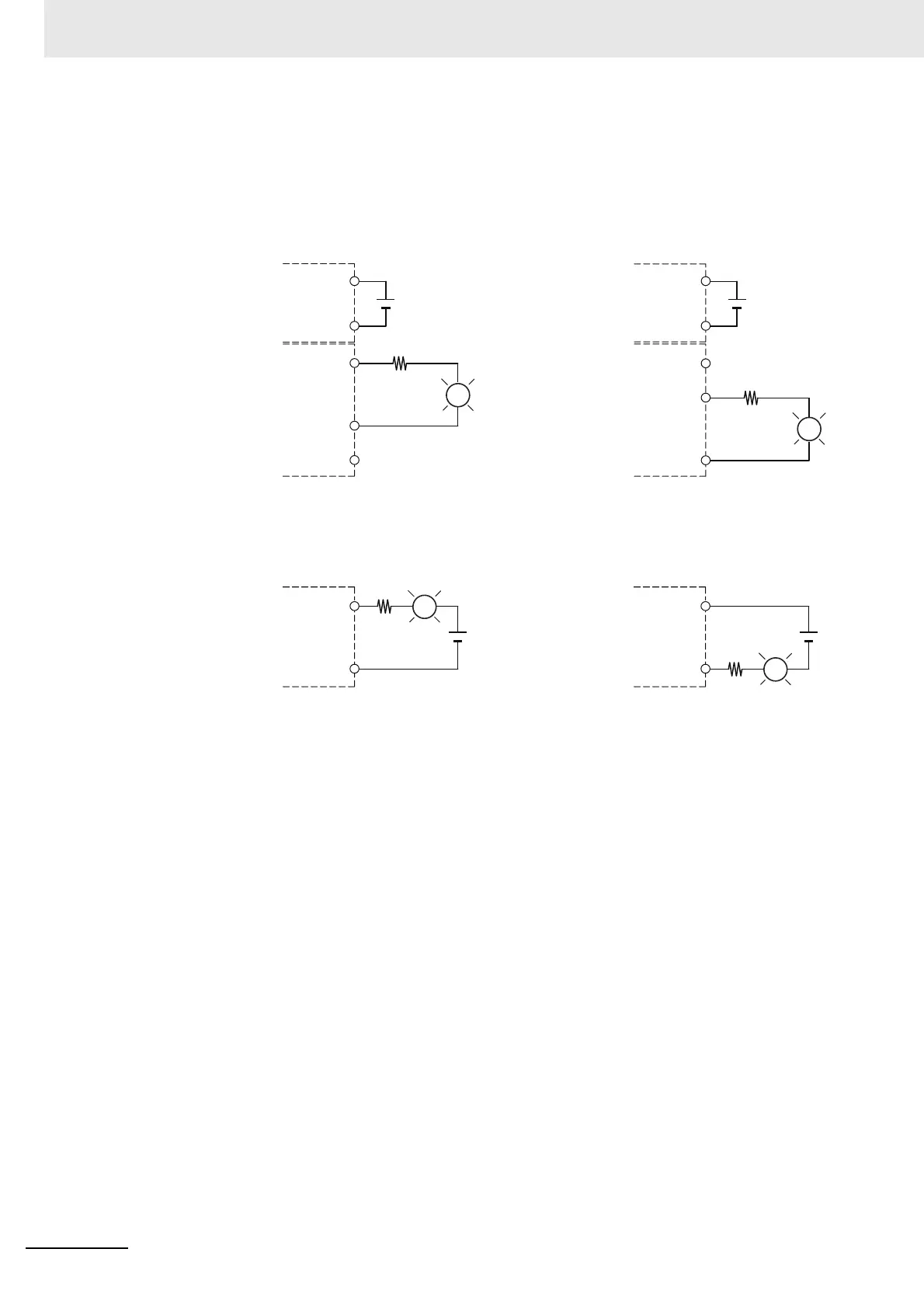
Countermeasure 2
Mount a limiting resistor.
When I/O power is supplied from the NX bus, the method is as shown in the following figure.
When I/O power is supplied from an external source, the method is as shown in the following figure.
In countermeasure 1, the current consumption from I/O power supply is increased although the voltage
supplied to the load L is not decreased.
In countermeasure 2, the voltage supplied to the load L is decreased although the current consumption
from I/O power supply is not increased.
Select the appropriate countermeasures according to the operating conditions.
IOG
IOV
IOG
IOV
OUT
IOG
IOV
IOG
IOV
OUT
NPN type PNP type
L
L
Transistor Output Unit
Communications
Coupler Unit or
Additional I/O Power
Supply Unit
Transistor Output Unit
Communications
Coupler Unit or
Additional I/O Power
Supply Unit
R
OUT
COM
+
Transistor Output Unit
NPN type PNP type
L
OUT
COM
+
Transistor Output Unit
L
R
 Loading...