5 - 33
5 I/O Refreshing
NX-series Digital I/O Unit User’s Manual (W521)
5-2 I/O Refreshing Methods
5
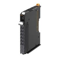
5-2-10 An Example of Turning ON Outputs at Specific Times After the Sensor Inputs Change
S
InputTimeStamp
<>
EN
In1
In2
State
UINT#0
=
EN
In1
In2
MOVE
EN
In
ENO
Out
InputTimeStamp
EN
In1
In2
OffsetTimeStamp
TmpWork
OffsetErrorTaskExeCnt
TaskPeriod
*
EN
In1
In2
ENO
Out
TmpWork
UINT#0
MOVE
EN
In
ENO
Out
State
ORD#16#1
MOVE
EN
In
ENO
Out
ErrorCode
<=
EN
In1
In2
OffsetTimeStamp
TmpWork
>
InputTimeStamp
OffsetTimeStamp
+
EN
In1
In2
ENO
Out
SetOutputTimeStamp
MOVE
EN
In
ENO
Out
S
Error
2_
utput_Bit_0
INT
MOVE
EN
In
ENO
Out
State
0 State0: Wait for input bit 00 to change.
If the specified time is 3 task periods or less, error end.
Transit to set the specified time and to check the output.
SetOutputTimeStamp
N1_Input_Bit_00_
Time_Stamp
N1_Input_Bit_00_
Time_Stamp
N2_Output_Bit_00_
Time_Stamp
R
>=
EN
In1
In2
State
UINT#1
=
EN
In1
In2
ULINT#0
MOVE
EN
In
ENO
Out
N2_Output_Bit_00_
Time_Stamp
UINT#0
MOVE
EN
In
ENO
Out
State
ErrorCode
S
Error
2_
utput_Bit_0
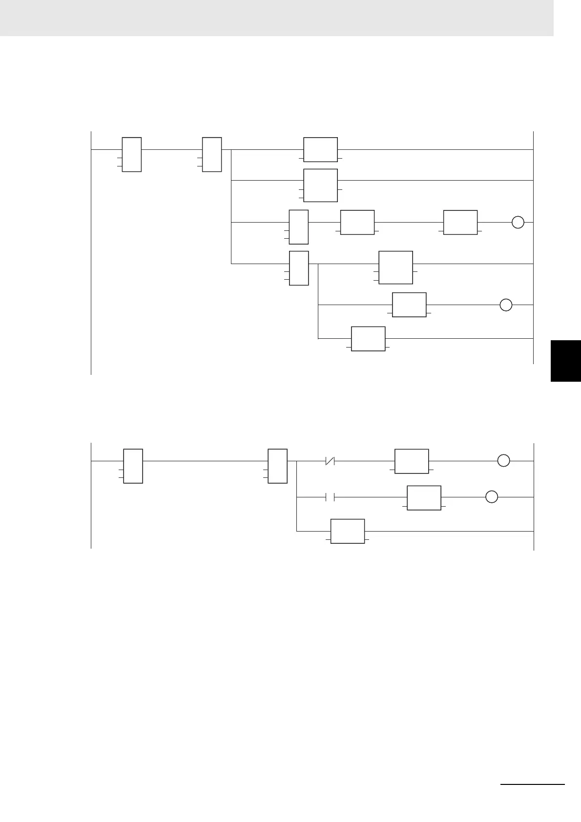
1 State1: Check the output.
Check the output status after the specified time has passed.
Output error or output completion (Turn OFF the output.).
N2_Output_Bit_00_
Output_Status
N2_Output_Bit_00_
Output_Status
W
RD
16
2
MOVE
EN
In
ENO
Out
E001_Time_Stamp_Synchronous_Output
SetOutputTimeStamp
 Loading...