A - 7
Appendices
NX-series Digital I/O Unit User’s Manual (W521)
A-1 Data Sheet
A
A-1-2 Digital Input Units
DC Input Units (Screwless Clamping Terminal Block, 12 mm Width)
Unit name
DC Input Unit
Model
NX-ID3317
Number of points
4 points
External connection
terminals
Screwless clamping terminal block (12 ter-
minals)
I/O refreshing method
Switching Synchronous I/O refreshing and Free-Run refreshing
Indicators
TS indicator, input indicators
Internal I/O common
NPN
Rated input voltage
12 to 24 VDC (9 to 28.8 VDC)
Input current
6 mA typical (at 24 VDC), rated current
ON voltage/ON current
9 VDC min./3 mA min. (between IOV and
each signal)
OFF voltage/OFF cur-
rent
2 VDC max./1 mA max. (between IOV and
each signal)
ON/OFF response time
20 μs max./400 μs max.
Input filter time
No filter, 0.25 ms, 0.5 ms, 1 ms (default), 2
ms, 4 ms, 8 ms, 16 ms, 32 ms, 64 ms, 128
ms, 256 ms
Dimensions
12 (W) x 100 (H) x 71 (D)
Isolation method
Photocoupler isolation
Insulation resistance
20 MΩ min. between isolated circuits (at
100 VDC)
Dielectric strength
510 VAC between isolated circuits for 1
minute at a leakage current of 5 mA max.
I/O power supply
method
Supply from the NX bus
Current capacity of I/O
power supply terminal
IOV: 0.1 A/terminal max., IOG
:
0.1 A/termi-
nal max.
NX Unit power con-
sumption
0.50 W max.
Current consumption
from I/O power supply
No consumption
Weight
65 g max.
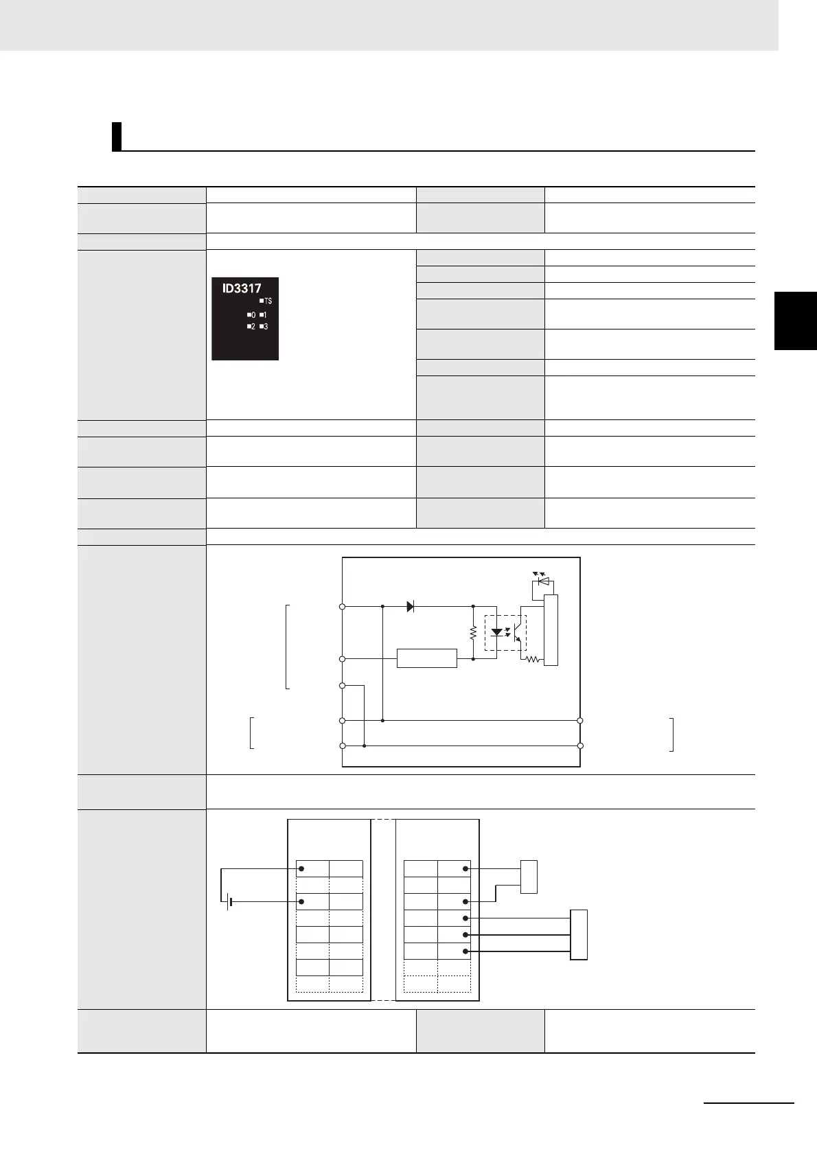
Circuit layout
Installation orienta-
tion and restrictions
Installation orientation: Possible in 6 orientations.
Restrictions: No restrictions
Terminal connection
diagram
Disconnec-
tion/Short-circuit
detection
Not supported. Protective function Not supported.
IOV0 to 3
IN0 to IN3
IOG0 to 3
NX bus
connector
(left)
Terminal block
I/O power supply +
I/O power supply −
Internal circuits
I/O power supply +
I/O power supply −
NX bus
connector
(right)
Current control
circuit
Additional I/O
Power Supply Unit
DC Input Unit
NX-ID3317
Two-wire
sensor
24 VDC
Three-wire
sensor
IOV
IOG
IOV
IOG
IOV
IOG
IOV
IOG
IN0
IOG0
IOV2
IOV0
A1 B1
A8 B8
IN2
IOG2
IN1
IOG1
IOV3
IOV1
IN3
IOG3
A1 B1
A8 B8
 Loading...