A - 25
Appendices
NX-series Digital I/O Unit User’s Manual (W521)
A-1 Data Sheet
A
A-1-3 Digital Output Units
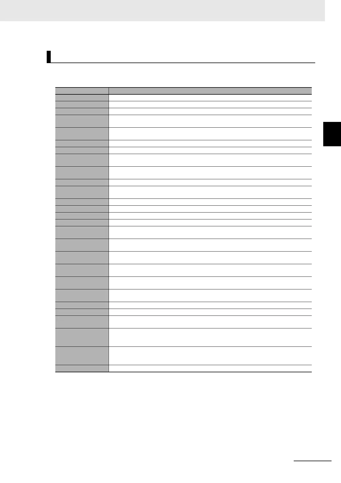
The meanings of the items on the data sheet of the Relay Output Unit are explained in the table below.
Description of Items on the Data Sheet of the Relay Output Unit
Item Description
Unit name The name of the Unit.
Model The model of the Unit.
Number of points The number of output points provided by the Unit.
External connection
terminals
The type of terminal block and connector that is used for connecting the Unit. The number of termi-
nals on the terminal block is also described when a screwless clamping terminal block is used.
I/O refreshing method The I/O refreshing methods that are used by the Unit. Free-Run refreshing and synchronous I/O
refreshing are available.
Indicators The type of indicators on the Unit and the layout of those indicators.
Relay type The type of relay that is connected to the Unit. There are N.O. and N.O. + N.C..
Maximum switching
capacity
The maximum value of switchable current of the connected relay.
Minimum switching
capacity
The minimum value of switchable current of the connected relay.
Relay service life The service life of the connected relay.
ON/OFF response
time
The delay time for which data in the internal circuit is reflected in the state of output elements of the
Unit. It is described according to the ON/OFF sequence.
Dimensions The dimensions of the Unit. They are described as W x H x D. The unit is "mm".
Isolation method The isolation method of the output circuit and internal circuit of the Unit.
Insulation resistance The insulation resistance between the output circuit and internal circuit of the Unit.
Dielectric strength The dielectric strength between the output circuit and internal circuit of the Unit.
Vibration resistance The vibration-resistance specifications of the Unit. Some are different from the general specifica-
tions.
Shock resistance These are the shock-resistance specifications of the Unit. Some are different from the general
specifications.
I/O power supply
method
The method for supplying I/O power to the Unit. The supply method is determined for each Unit.
The power is supplied from the NX bus or the external source.
Current capacity of I/O
power supply terminal
The current capacity of the I/O power supply terminals (IOV/IOG) of the Unit. Do not exceed this
value when supplying the I/O power to the connected external devices.
NX Unit power con-
sumption
The power consumption of the NX Unit power supply of the Unit.
Current consumption
from I/O power supply
The current consumption from I/O power supply of the Unit. The load current of any external con-
nection load and current consumption of any connected external devices are not included.
Weight The weight of the Unit.
Circuit layout The output circuit layout of the Unit.
Installation orienta-
tion and restrictions
The installation orientation of the Slave Terminal including the Unit, and the details of restrictions
on the specifications due to the installation orientation.
Terminal connection
diagram
A diagram of the connection between the Unit and connected external devices. When an I/O
Power Supply Connection Unit or a Shield Connection Unit is required to be connected to the con-
nected external devices, the description for such is included.
Disconnec-
tion/Short-circuit
detection
The function of the Unit to detect a disconnection/short-circuit.
Protective function The protective function that the Unit has.
 Loading...