Appendices
A - 42
NX-series Digital I/O Unit User’s Manual (W521)
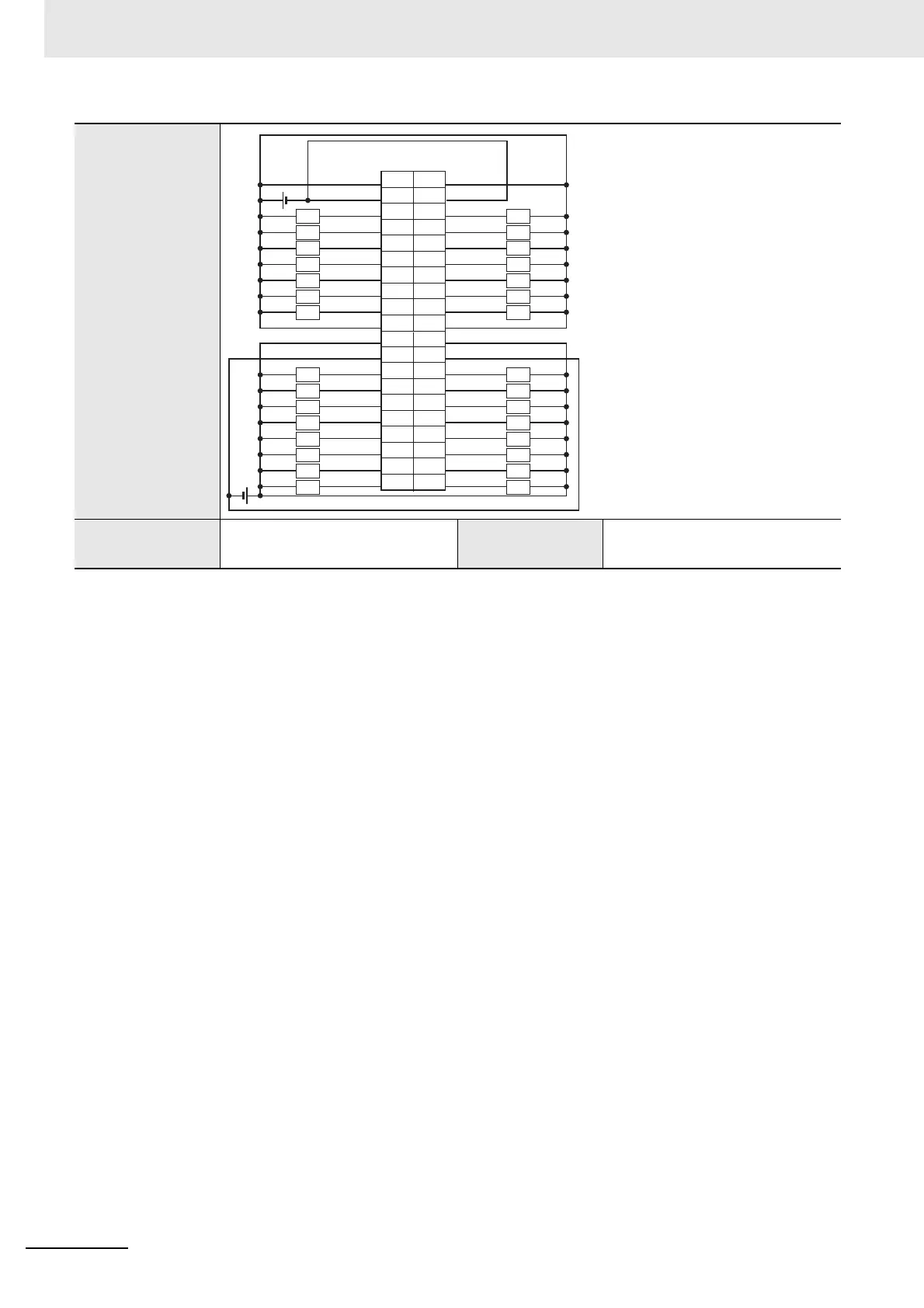
Terminal connection
diagram
Disconnec-
tion/Short-circuit
detection
Not supported. Protective function Not supported.
1
5
9
3
7
11
15
17
19
13
+V1
OUT31
OUT29
COM1
OUT30
OUT28
OUT26
OUT25
OUT24
OUT27
2
6
10
4
8
12
16
18
20
14
21
25
29
23
27
31
35
37
39
33
22
26
30
24
28
32
36
38
40
34
+V1
OUT23
OUT21
COM1
OUT22
OUT20
OUT18
OUT17
OUT16
OUT19
+V0
OUT15
OUT13
COM0
OUT14
OUT12
OUT10
OUT09
OUT08
OUT11
+V0
OUT07
OUT05
COM0
OUT06
OUT04
OUT02
OUT01
OUT00
OUT03
L
L
L
L
L
L
L
L
L
L
L
L
L
L
L
L
L
L
L
L
L
L
L
L
L
L
L
L
L
L
Connector
pin
Signal
name
Signal
name
• Be sure to wire both pins 21
and 22 (+V0).
• Be sure to wire both pins 23
and 24 (COM0).
• Be sure to wire both pins 1
and 2 (+V1).
• Be sure to wire both pins 3
and 4 (COM1).
 Loading...