A - 47
Appendices
NX-series Digital I/O Unit User’s Manual (W521)
A-1 Data Sheet
A
A-1-3 Digital Output Units
Unit name
Relay Output Unit
Model
NX-OC2733
Number of points 2 points, independent contacts
External connection
terminals
Screwless clamping terminal block (8 ter-
minals)
I/O refreshing method
Free-Run refreshing
Indicators
TS indicator, output indicator
Relay type
N.O. + N.C. contact
Maximum switching
capacity
250 VAC/2 A (cosΦ = 1),
250 VAC/2 A (cosΦ = 0.4),
24 VDC/2 A,
4 A/NX Unit
Minimum switching
capacity
5 VDC, 10 mA
Relay service life
Electrical: 100,000 operations
*1
Mechanical: 20,000,000 operations
ON/OFF response time
15 ms max./15 ms max.
Dimensions
12 (W) ×100 (H) ×71 (D)
Isolation method
Relay isolation
Insulation resistance
Between A1/3, B1/3 terminals and A5/7,
B5/7 terminals: 20 MΩ min. (
at
500 VDC)
Between the external terminals and func-
tional ground terminal: 20 MΩ min. (
at
500 VDC)
Between the external terminals and inter-
nal circuits: 20 MΩ min. (
at
500 VDC)
Between the internal circuit and the func-
tional ground terminal: 20 MΩ min. (
at
100 VDC)
Dielectric strength
Between A1/3, B1/3 terminals and A5/7,
B5/7 terminals: 2300 VAC for 1 min at a
leakage current of 5 mA max.
Between the external terminals and the
functional ground terminal: 2300 VAC for
1 min at a leakage current of 5 mA max.
Between the external terminals and inter-
nal circuits: 2300 VAC for 1 min at a leak-
age current of 5 mA max.
Between the internal circuit and the func-
tional ground terminal: 510 VAC for 1 min
at a leakage current of 5 mA max.
Vibration resistance
10 to 55 Hz with amplitude of 0.5 mm
Shock resistance
50 m/s
2
, 3 times each in X, Y, and Z
directions
I/O power supply
method
Supply from external source
Current capacity of I/O
power supply terminal
Without I/O power supply terminals
NX Unit power con-
sumption
0.95 W max. Current consumption
from I/O power supply
No consumption
Weight
70 g max.
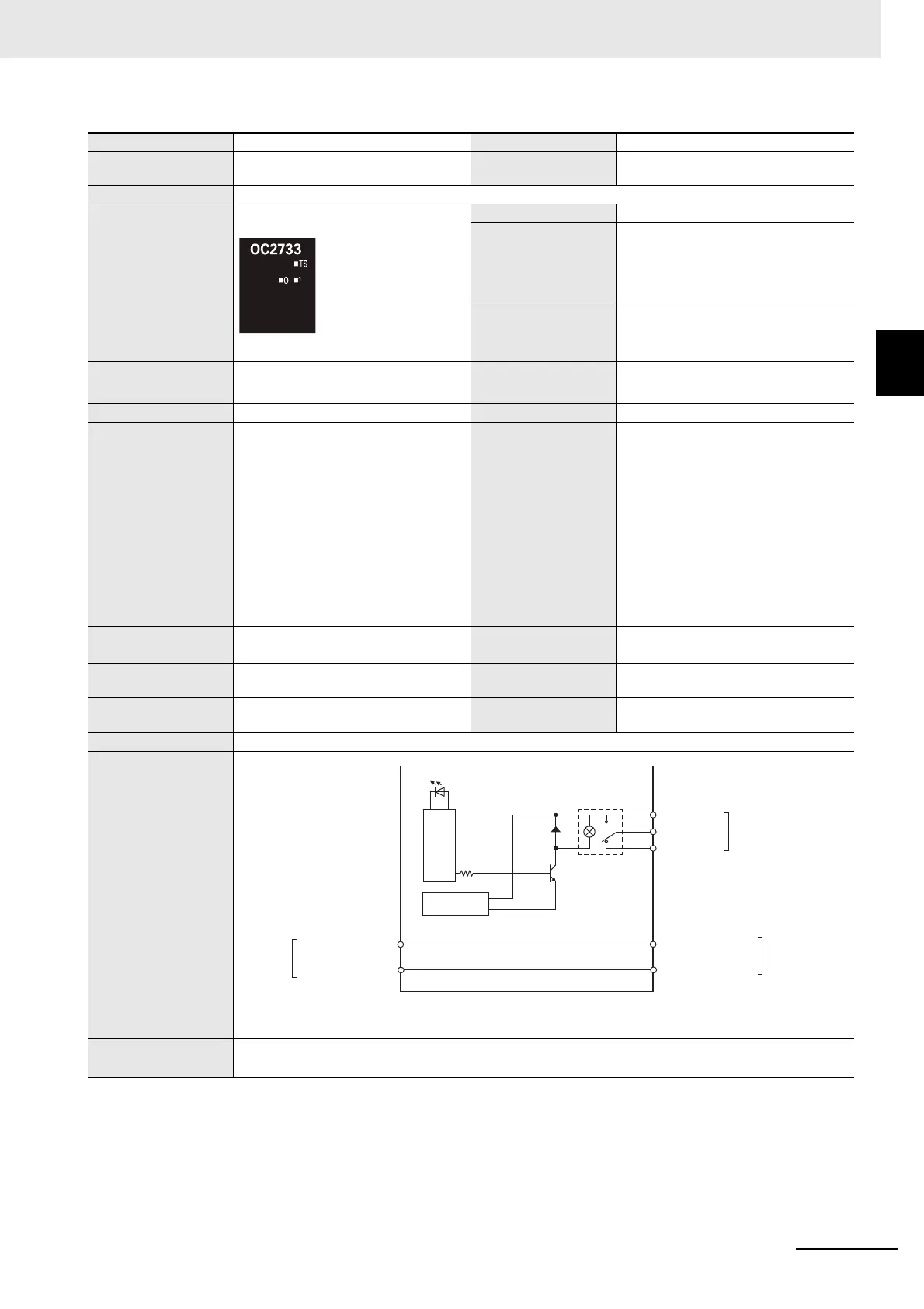
Circuit layout
Installation orienta-
tion and restrictions
Installation orientation: Possible in 6 orientations.
Restrictions: No restrictions
NO0 to NO1
NC0 to NC1
Internal circuits
Internal power
supply
NO0 and NO1 are normally open contacts, and NC0 and NC1 are normally close contacts.
You cannot replace the relay.
Terminal block
I/O power supply +
I/O power supply −
I/O power supply +
I/O power supply −
NX bus
connector
(left)
NX bus
connector
(right)
C0 to C1
 Loading...