Appendices
A - 54
NX-series Digital I/O Unit User’s Manual (W521)
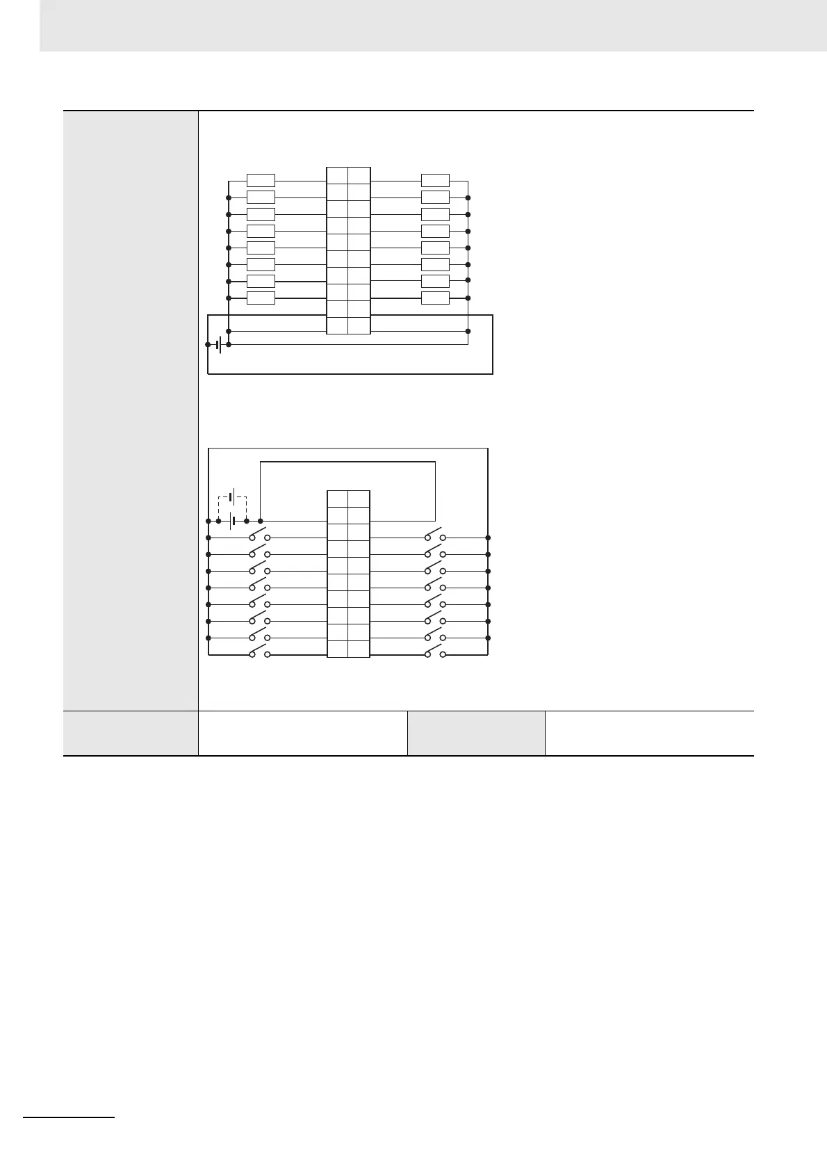
Terminal connection
diagram
Disconnec-
tion/Short-circuit
detection
Not supported.
Protective function Not supported.
20
16
12
18
14
10
6
4
2
8
OUT0
OUT2
OUT4
OUT1
OUT3
OUT5
OUT7
COM0
+V0
OUT6
19
15
11
17
13
9
5
3
1
7
12 to 24 VDC
OUT8
OUT10
OUT12
OUT9
OUT11
OUT13
OUT15
COM0
+V0
OUT14
L
L
L
L
L
L
L
L
L
L
L
L
L
L
L
L
CN1 (left) output terminal
• Be sure to wire both pins 3 and 4 (COM0) of CN1.
• Be sure to wire both pins 1 and 2 (+V0) of CN1.
• The polarity of the input power supply of CN2 can be connected in either direction.
• Be sure to wire both pins 3 and 4 (COM1) of CN2, and set the same polarity for both pins.
1
5
9
3
7
11
15
17
19
13
NC
IN15
IN13
COM1
IN14
IN12
IN10
IN09
IN08
IN11
2
6
10
4
8
12
16
18
20
14
NC
IN07
IN05
COM1
IN06
IN04
IN02
IN01
IN00
IN03
24 VDC
CN2 (right) input terminal
Connector
pin
Signal
name
Signal
name
Connector
pin
Signal
name
Signal
name
 Loading...