A - 69
Appendices
NX-series Digital I/O Unit User’s Manual (W521)
A-3 Connecting Connector-Terminal Block
Conversion Units and I/O Relay Terminals
A
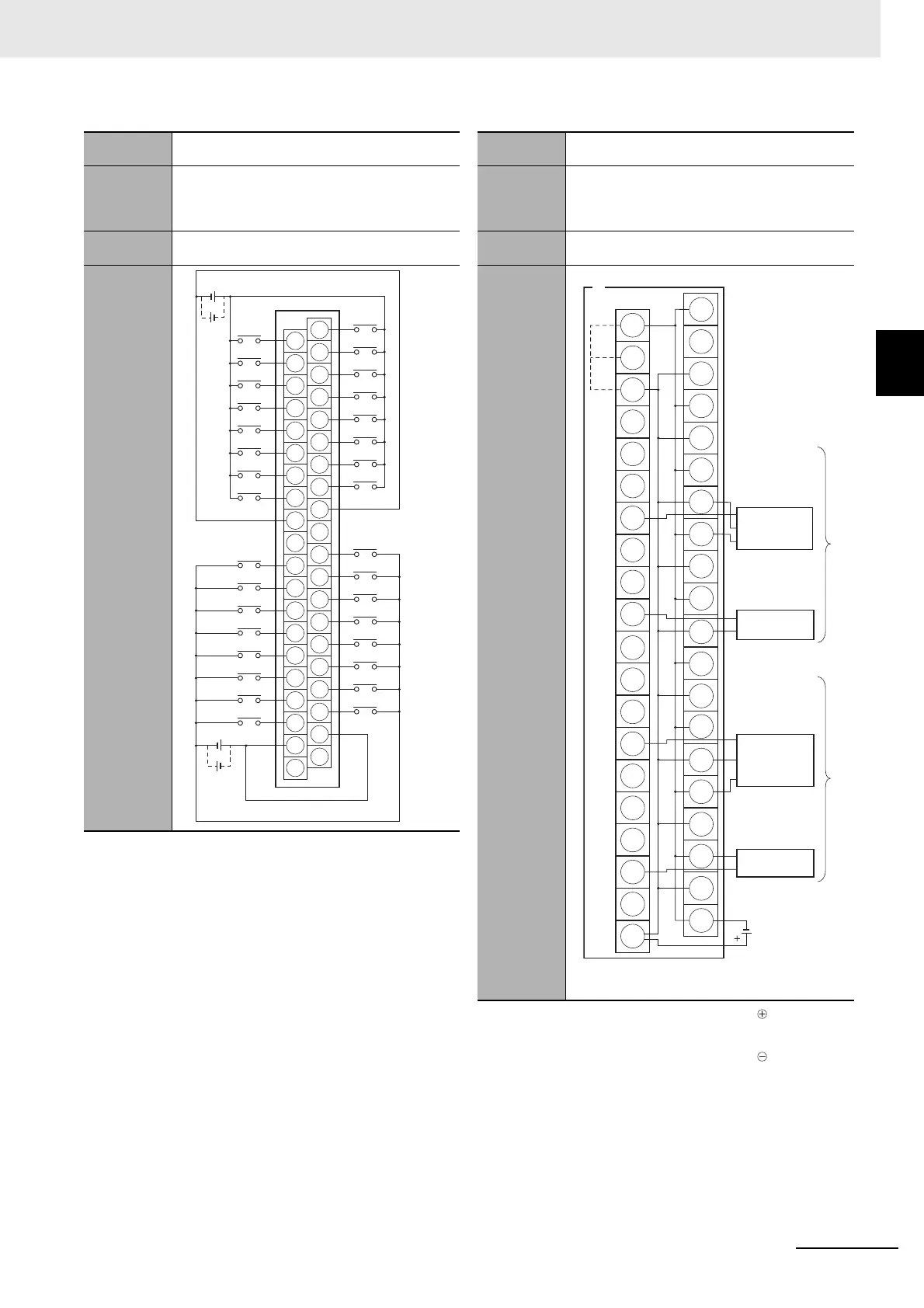
A-3-3 Connector-Terminal Block Conversion Unit Connection Diagrams
Note 1. The polarity for input power supply connections
indicated with dotted lines (
-
-
-
-
-
) can be con-
nected in either direction provided that the same
polarity is used for the commons.
2. Both COM0 and COM1 have two pins each. They
are internally connected inside the Unit, but they
must all be wired.
Note 1. Connect the A9/B9 terminal and the terminal for
NPN.
Connect the A9/B9 terminal and the terminal for
PNP.
(Use the enclosed short bar.)
2. The COM terminals are wired inside the Connec-
tor-Terminal Block Conversion Unit.
Digital I/O
Unit
NX-ID6142-5
Connec-
tor-Terminal
Block Con-
version Unit
XW2D-40G6
XW2D-40G6-RM
Connecting
Cable
XW2Z-
K
Connection
diagram
A20
A11
A12
A13
A14
A15
A16
A17
A18
A19
B20
B11
B12
B13
B14
B15
B16
B17
B18
B19
A10
A1
A2
A3
A4
A5
A6
A7
A8
A9
B10
B1
B2
B3
B4
B5
B6
B7
B8
B9
08
09
10
11
12
13
14
15
09
08
10
11
12
13
14
15
00
01
02
03
04
05
06
07
00
NC
NC
NC
NC
COM0
COM0
COM1
COM1
01
02
03
04
05
06
07
24 VDC
24 VDC
Wd (m+1)
Wd m
Digital I/O
Unit
NX-ID6142-5
Connec-
tor-Terminal
Block Con-
version Unit
XW2C-20G6-IO16 (2 Units)
Connecting
Cable
XW2Z-
N
Connection
diagram
0
1
2
3
4
5
6
7
8
9
10
11
12
13
14
15
A9
B9
A10
B10
(Short bar)
+
−
−
+
−
−
+
+
+
−
−
+
+
−
−
+
−
+
+
−
−
+
24 VDC
Black (White)
Brown (Red)
Blue (Black)
Black (White)
Brown (Red)
Blue (Black)
Blue (Black)
Brown (White)
Wd m
(Wd (m+1))
*1. PNP
*2. NPN
3-wire sensor with
PNP output
(photoelectric
sensor or
proximity sensor)
3-wire sensor
with NPN output
(photoelectric
sensor or
proximity sensor)
2-wire sensor
(e.g., limit switch)
2-wire sensor
(e.g., limit switch)
Blue (Black)
Brown (White)
*1
*2
 Loading...