6. Contact Signal ratings
●
Signal output (BL, TR, BU, WB, BU)
●
UPS Stop Signal input (BS)
Photo coupler ratings Input voltage HIGH(ON) 5 to 12 VDC
Appliable voltage: 35 VDC or less LOW(OFF) 0.7 VDC or less
Maximum current: 20 mA
●
Remote ON/OFF
Voltage between terminals: 5 VDC
Current when closed: max.10 mA
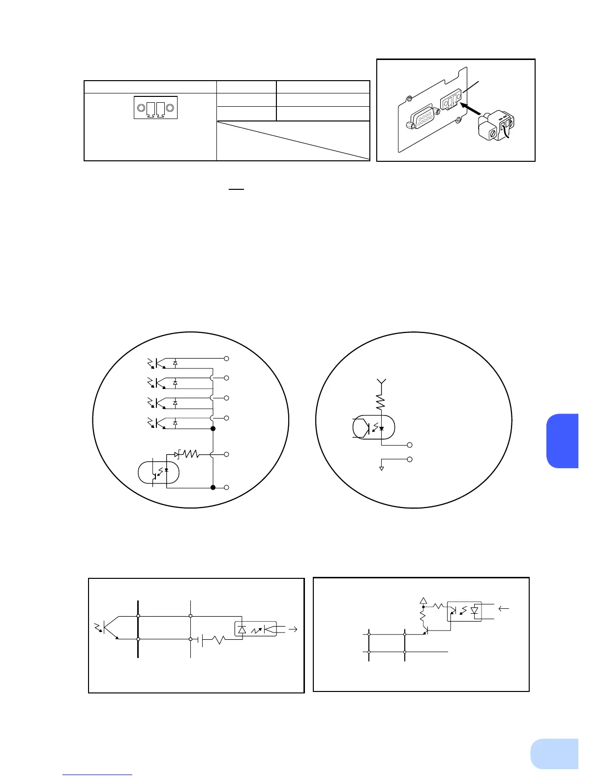
7. Contact Signal circuit inside the UPS
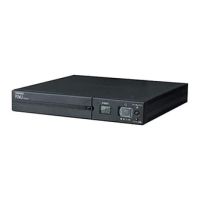
5. Remote ON/OFF connector
Front view
Screw size: Inch screw
#4-40 UNC
Pin assignment
Pin number
Signal name
1
Remote ON/OFF (+)
2
Remote ON/OFF (-)
1
2
8. Example of the use of the Contact Signal circuit
●
Example of BU signal output circuit and
the connected circuit
●
Example of BS signal input circuit and the
connected circuit
COM
UPS side
BU
12V1K
TLP627
To port on PC
System side
Connecting cable
(twisted or shielded)
BL
TR
BU
WB
BS
COM
2.4V 560Ω
Remote ON/OFF (+)
Remote ON/OFF (-)
5V
10kΩ
COM
UPS side
GND
System side
Connecting cable
(twisted or shielded)
BS
12V
1K
1.2K
TLP521
From port on PC
Connect the included
remote ON/OFF connector
Connector