Caution
4. Signal I/O card
4-1 Signal Output
The card unit has 4 kinds of output signals.
Reverse output or normal output can be set for each signal output, and all signals are set to the reverse output
when shipped from the factory. The signal output is a relay contact output.
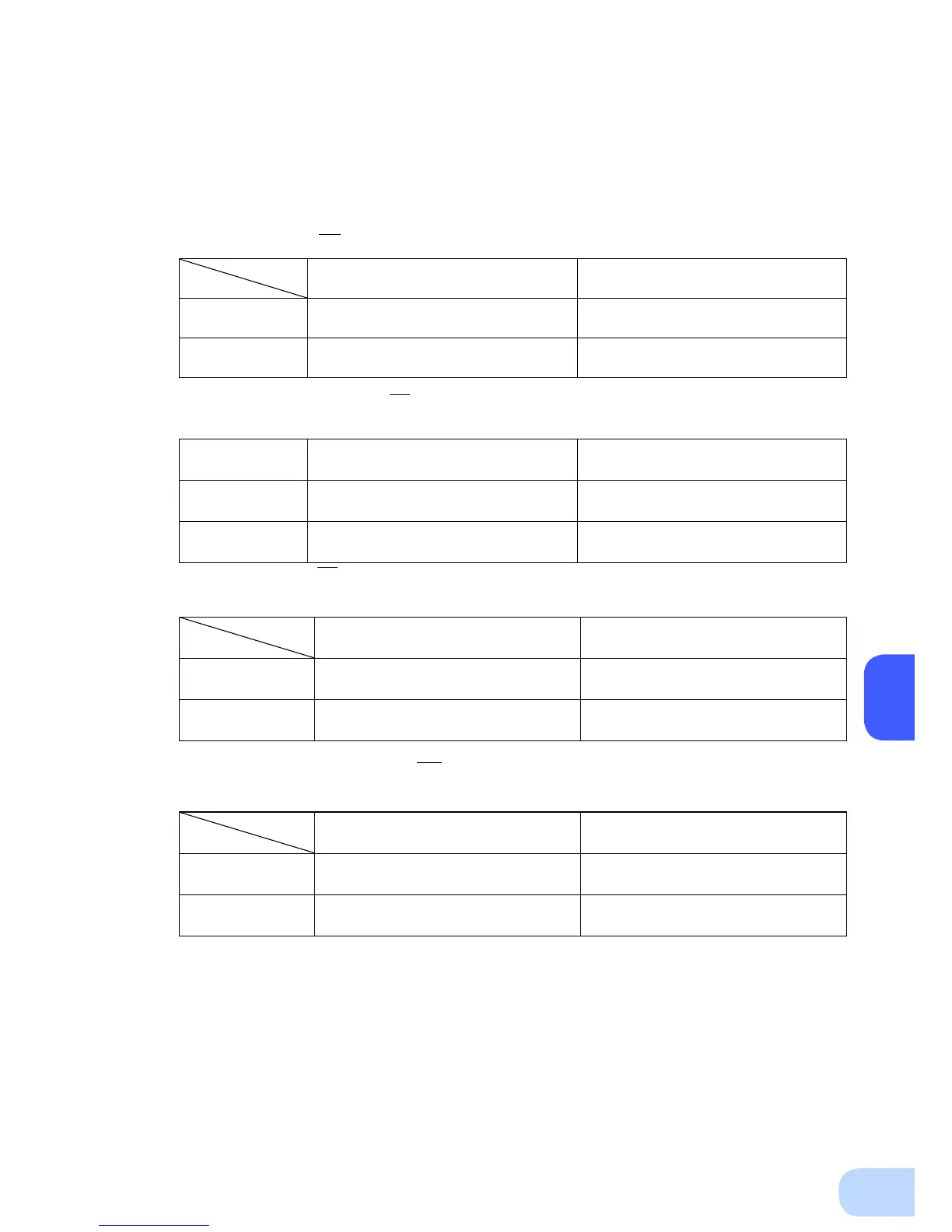
●BackupSignaloutput(BU,BU)
Reverse output setting
(Factory setting)
Normal output setting
Battery mode
Open between pins 1 and 2 of the
signal output connector
Short circuit between pins 1 and 2 of
the signal output connector
Normal mode
Short circuit between pins 1 and 2 of
the signal output connector
Open between pins 1 and 2 of the
signal output connector
●Lowbatterylevelsignaloutput:(BL,BL)
This signal indicates that the UPS is in battery mode operation.
Reverse output setting
(Factory setting)
Normal output setting
Low battery level
Open between pins 3 and 4 of the
signal output connector
Short circuit between pins 3 and 4 of
the signal output connector
Normal mode
Short circuit between pins 3 and 4 of
the signal output connector
Open between pins 3 and 4 of the
signal output connector
●TroubleSignaloutput(TR,TR)
This signal indicates that an internal abnormality has occurred in the UPS.
Reverse output setting
(Factory setting)
Normal output setting
Internal abnormality
Open between pins 5 and 6 of the
signal output connector
Short circuit between pins 5 and 6 of
the signal output connector
Normal mode
Short circuit between pins 5 and 6 of
the signal output connector
Open between pins 5 and 6 of the
signal output connector
●BatteryReplacementSignaloutput(WB,WB)
This signal indicates that the necessity of exchanging the battery has been detected by the test.
Reverse output setting
(Factory setting)
Normal output setting
Exchanging the
battery is detected
Open between pins 6 and 7 of the
signal output connector
Short circuit between pins 6 and 7 of
the signal output connector
Normal mode
Short circuit between pins 6 and 7 of
the signal output connector
Open between pins 6 and 7 of the
signal output connector