Parameter Details
12
12.6 F: OPTIONS
SIEPYEUOQ2A01A AC Drive Q2A Technical Manual 633
If the drive does not detect output pulses from the encoder for longer than the time set in F1-14, the drive will
detect PGo.
Note:
Motor speed and load conditions can cause ov [Overvoltage] and oC [Overcurrent] faults.
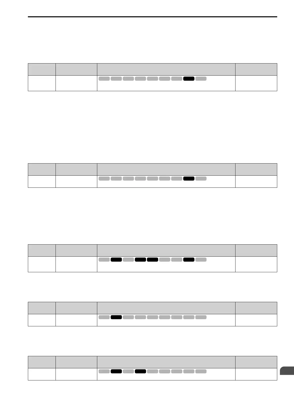
■ F1-18 Dev3 Mode Selection
No.
(Hex.)
Name Description
Default
(Range)
F1-18
(03AD)
Dev3 Mode Selection
Sets the number of rotations necessary to detect conditions that invert the torque reference and
rate of acceleration and cause dv3 [Inversion Detection].
10
(0 - 10)
When the drive detects these two conditions at the same time for the number of times set in F1-18, the drive will
detect dv3.
• The torque reference and acceleration are in opposite directions. For example, torque reference is in forward run
and the acceleration is in a negative direction.
• The difference between the speed reference and the actual motor speed is more than 30%.
Note:
• Reference the setting value for E5-11 [Enc ZPulse Offset] and the δθ value found on the motor nameplate. A usual cause for a dv3 fault
is an incorrect E5-11 setting.
• Set F1-18 = 0 to disable the function.
■ F1-19 Dev4 Mode Selection
No.
(Hex.)
Name Description
Default
(Range)
F1-19
(03AE)
Dev4 Mode Selection
Sets the number of pulses necessary to cause dv4 [Inversion Prevention Detection].
128
(0 - 5000)
The drive detects a dv4 [Inversion Prevention Detection] fault when the pulses in a reverse direction to the speed
reference are input for longer than the time set in F1-19.
Note:
• Refer to the E5-11 [Enc ZPulse Offset] value and the Δθ value shown on the motor nameplate. An incorrect E5-11 value will frequently
be the cause of a dv4 fault.
• When you use the drive in an application that rotates the motor from the load side in the reverse direction of the speed reference, set
F1-19 = 0.
■ F1-20 Enc1 PCB Disconnect Detect
No.
(Hex.)
Name Description
Default
(Range)
F1-20
(03B4)
Enc1 PCB Disconnect
Detect
Sets the function that enables and disables detection of a disconnected encoder connection cable
to cause PGoH [Encoder (PG) Hardware Fault].
1
(0, 1)
0 : Disabled
1 : Enabled
■ F1-21 Enc1 Signal Selection
No.
(Hex.)
Name Description
Default
(Range)
F1-21
(03BC)
Enc1 Signal Selection
Sets the number of channels for the signal to the encoder option card.
0
(0, 1)
0 : A Pulse Detection
1 : AB Pulse Detection
■ F1-30 M2 Enc PCB Port Select
No.
(Hex.)
Name Description
Default
(Range)
F1-30
(03AA)
M2 Enc PCB Port Select
Sets the drive port to install the motor 2 encoder option card.
1
(0, 1)
 Loading...


