12.7 H: TERMINALS
698 SIEPYEUOQ2A01A AC Drive Q2A Technical Manual
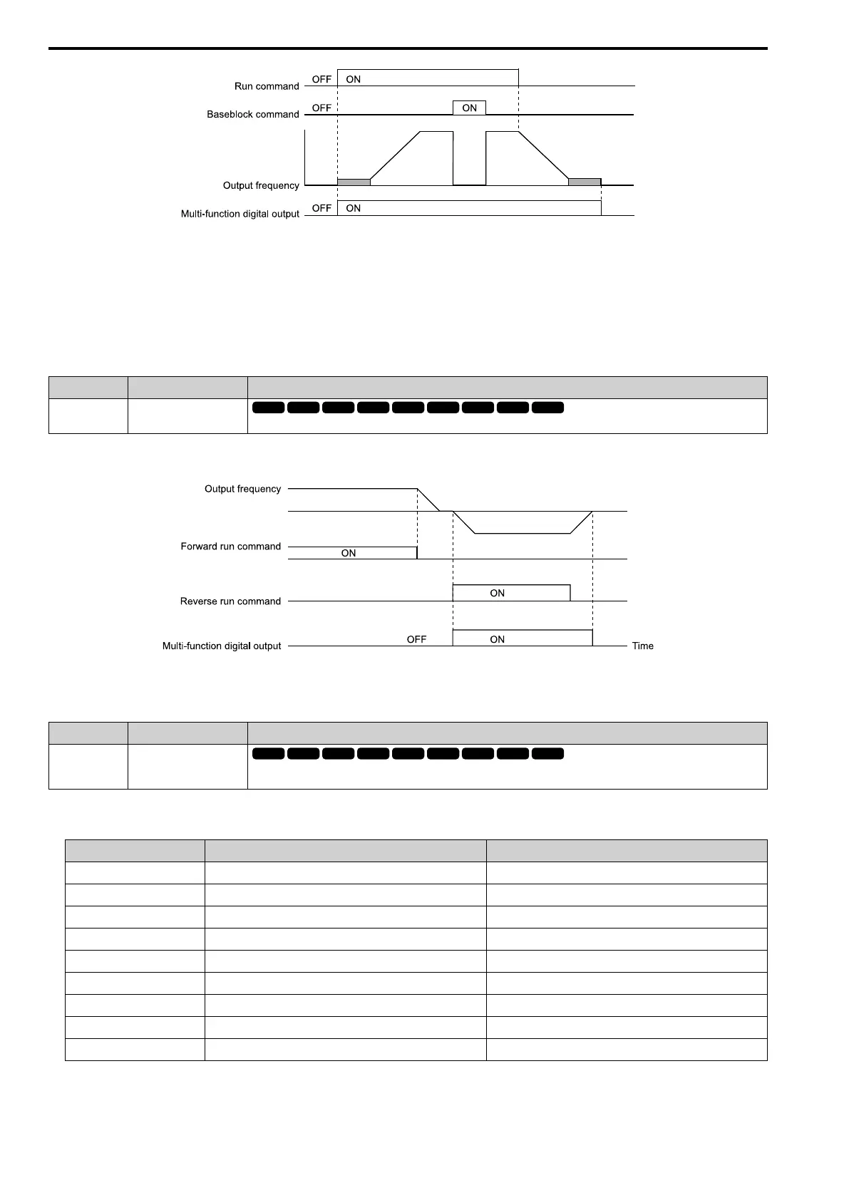
Figure 12.84 Drive Running Time Chart
ON : Drive is running
Drive is operating or making voltage.
OFF : Drive is stopping
Drive is stopped.
■ 6: @Reverse
Setting Function Description
6 @Reverse
The terminal activates when the motor operates in the reverse direction.
ON : The motor is operating in the reverse direction.
OFF : The motor is operating in the forward direction or the motor stopped.
Figure 12.85 Reverse Operation Output Time Chart
■ 7: Zero Speed
Setting Function Description
7 Zero Speed
The terminal activates when the output frequency is less than the value of E1-09 [Min Output Frequency] or b2-01 [ZSpd/DCI
Threshold].
Note:
A1-02 [Control Method] selects which parameter is the reference.
A1-02 Setting Control Method Parameter Used as the Reference
0 V/f Control E1-09
1 PG V/f Control E1-09
2 OLVector b2-01
3 CLVector E1-09
4 Adv OLVector E1-09
5 PM OLVector E1-09
6 PM AOLVector E1-09
7 PM CLVector b2-01
8 EZ Vector E1-09
 Loading...


