12.7 H: TERMINALS
722 SIEPYEUOQ2A01A AC Drive Q2A Technical Manual
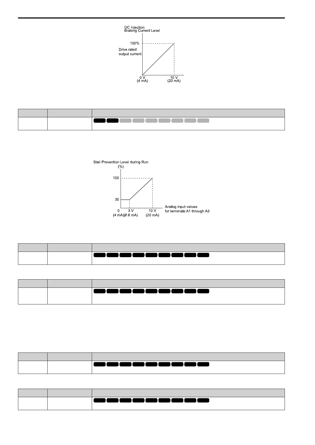
Figure 12.105 DC Injection Braking Current through Analog Input
■ 14: StallPLev@Rn
Setting Value Function Description
14 StallPLev@Rn
Enters a signal to adjust the stall prevention level during run if the drive rated current is 100%.
Note:
The correct stall prevention level during run is the lower value between:
• The analog input value for the MFAI terminal, or
• The value of L3-06 [StallP Level@Run].
Figure 12.106 Stall Prevention Level during Run through Analog Input
■ 15: OutFLowLimSel
Setting Function Description
15 OutFLowLimSel
Enters a signal to adjust the output frequency lower limit level if E1-04 [Max Output Frequency] = 100%.
■ 16: Mot PTC Input
Setting Function Description
16 Mot PTC Input
Uses the motor Positive Temperature Coefficient (PTC) thermistor to prevent heat damage to the motor if the current value
when the 10 V (or 20 mA) analog signal is input is 100%.
• You can use the Positive Temperature Coefficient (PLC) thermistor as an auxiliary or alternative detection
function for oL1 [Motor Overload] problems to help prevent heat damage to motors. If the PTC input signal is
more than the overload alarm level, oH3 [Motor Overheating Alarm] will flash on the keypad.
• When the drive detects oH3, the motor stops with the setting in L1-03. When the drive detects oH4, the motor
stops with the setting in L1-04. When the drive incorrectly detects motor overheating problems, set L1-05.
■ 30: Q2pack AI1
Setting Function Description
30 Q2pack AI1
Use with Q2pack. Refer to the Q2pack online manual for more information.
■ 31: Q2pack AI2
Setting Function Description
31 Q2pack AI1
Use with Q2pack. Refer to the Q2pack online manual for more information.
 Loading...


