3 Specifications
3 - 126
AC Servomotors/Servo Drives 1S-series with Built-in EtherCAT® Communications User’s Manual (I586)
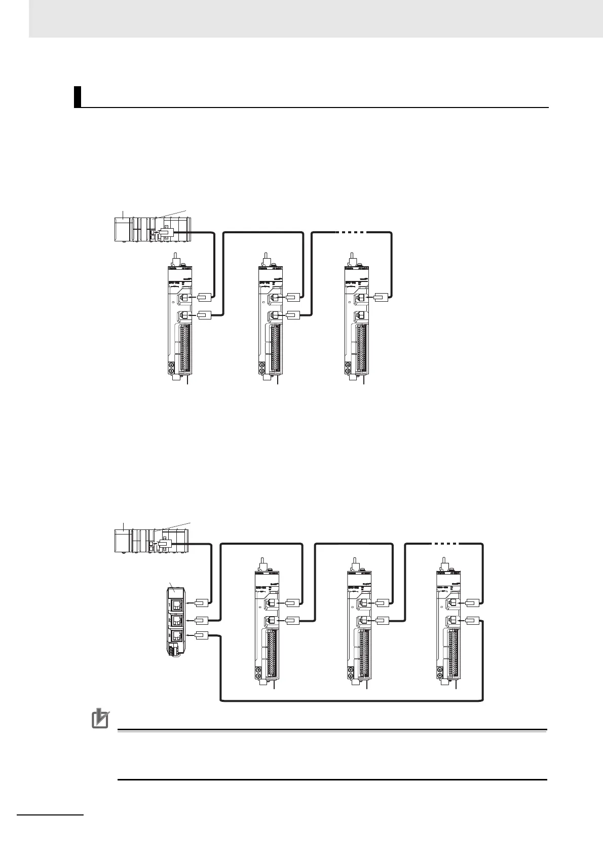
Wiring Example of Configuring Daisy Chain Topology
This example shows how to connect an NJ/NX-series CPU Unit to Servo Drives by the use of Ether-
CAT Communications Cables. Connect the NJ/NX-series CPU unit to the ECAT IN connector on the
first Servo Drive. Connect the ECAT OUT connector on the first Servo Drive to the ECAT IN connec-
tor on the next Servo Drive. Do not connect the ECAT OUT connector on the last Servo Drive.
Wiring Example of Configuring Ring Topology
This example shows how to connect an NJ/NX-series CPU Unit to Servo Drives via an OMRON
GX-JC03 EtherCAT Junction Slave by the use of EtherCAT Communications Cables. Connect the
NJ/NX-series CPU unit to the IN connector on the EtherCAT Junction Slave. Connect the X2 con-
nector (start port of the ring) on the EtherCAT Junction Slave to the ECAT IN connector on the first
Servo Drive. Connect the ECAT OUT connector on the first Servo Drive to the ECAT IN connector
on the next Servo Drive. Connect the ECAT OUT connector on the last Servo Drive to the X3 con-
nector (end port of the ring) on the EtherCAT Junction Slave.
Precautions for Correct Use
• Always turn OFF the power supply to the NJ/NX-series CPU Unit and Servo Drives before
you connect or disconnect the EtherCAT Communications Cables.
• The cable between the two nodes (L1, L2 ... Ln) must be 100 m or less.
Wiring
RUN IN OUT
FS
L/A L/A
ERR
RUN IN OUT
FS
L/A L/A
ERR
RUN IN OUT
FS
L/A L/A
ERR
L1 L2 Ln
Power supply unit
NJ/NX-series
CPU Unit
RUN IN OUT
FS
L/A L/A
ERR
RUN IN OUT
FS
L/A L/A
ERR
RUN IN OUT
FS
L/A L/A
ERR
L1 L2 L4
Ln
L3
Power supply unit
NJ/NX-series
CPU Unit
EtherCAT
Junction Slave
IN
X2
X3
 Loading...

