3 - 19
3 Specifications
AC Servomotors/Servo Drives 1S-series with Built-in EtherCAT® Communications User’s Manual (I586)
3-1 Servo Drive Specifications
3
3-1-4 Main Circuit and Motor Connections
Control Circuit Connector (CND) Specifications
Motor Connector (CNC) Specifications
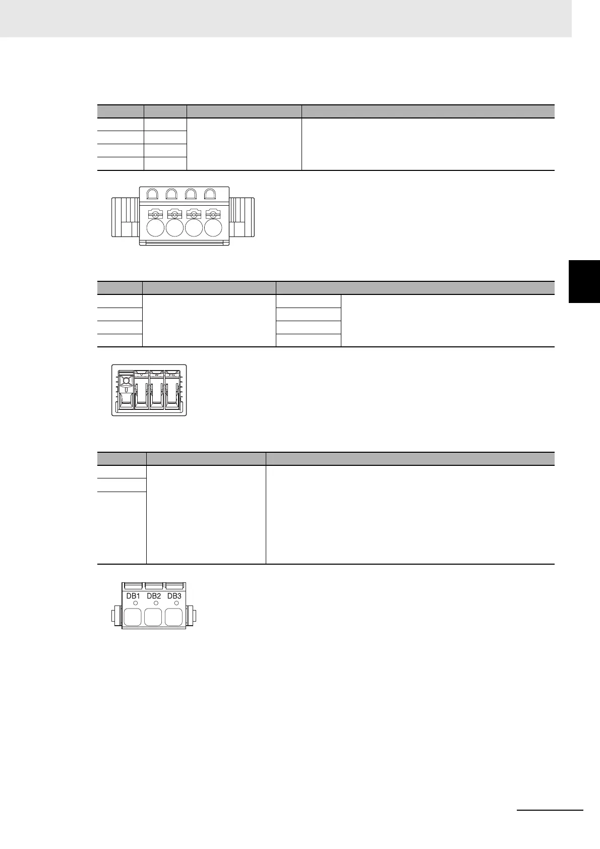
Main Circuit Connector E (CNE) Specifications
Pin No. Symbol Name Specifications
1 +24V Control circuit power sup-
ply input
24VDC (21.6 to 26.4 V)
Measured current value: 1,200 mA
2+24V
30 V
40 V
Symbol Name Specifications
U Motor connection terminals Phase U These are output terminals to the Servomotor.
V Phase V
W Phase W
FG FG
Symbol Name Specifications
DB1 External Dynamic Brake
Resistor connection termi-
nals
When the Internal Dynamic Brake Resistor is used:
• Open between DB1 and DB2.
• Short-circuit DB2 and DB3.
When the External Dynamic Brake Resistor is used:
• Connect the External Dynamic Brake Resistor between DB1 and
DB2.
• Open between DB2 and DB3.
DB2
DB3