8-40
8-5 Interface Monitor Setting Parameters
OMNUC G5-SERIES AC SERVOMOTOR AND SERVO DRIVE USER'S MANUAL
8
Parameter Details
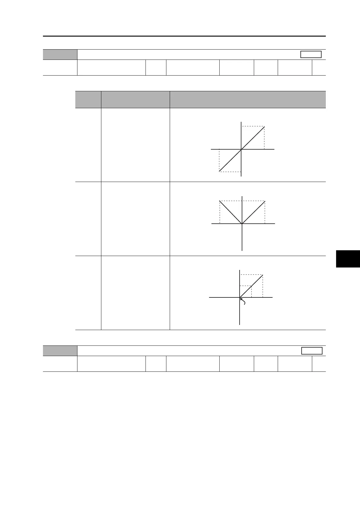
Select the analog monitor output voltage direction.
When monitor type is motor speed and gain of conversion is 500 (1 V = 500 r/min)
Adjust the offset of the speed command input (REF: CN1 pin 14).
The offset amount is approx. the set value times 0.359 mV.
There are 2 ways to adjust the offset.
· Manual adjustment
· Automatic adjustment
The manual adjustment is as follows:
·
To adjust the offset for individual drives, accurately input 0 V to the speed command input/torque command input
(REF/TREF1) (or connect to the signal ground), and then set this parameter so that the motor does not rotate.
· If you use a position loop in the host device, set this parameter so that there are no
accumulated pulses at servo lock stop status.
The automatic adjustment is as follows:
This parameter will be automatically set when automatic offset adjustment is executed. Refer to
"Analog Input Automatic Offset Adjustment" (P.9-26) for the automatic offset adjustment method.
Pn421
Analog Monitor Output Selection
Setting
range
0 to 2 Unit −
Default
setting
0
Power OFF
and ON
−
Set
value
Output range Data output
0 −10 to 10 V
1 0 to 10 V
2 0 to 10 V
10 V
−
10 V
0 V
−
5,000
5,000 [r/min]
Motor
speed
Output voltage [V]
10 V
−
10 V
0 V
−
5,000
5,000 [r/min]
Motor
speed
Output voltage [V]
10 V
5 V
−
10 V
0 V 0
−
2,500
2,500 [r/min]
Motor
speed
Output voltage [V]
Pn422
Analog Input 1 Offset
Setting
range
−5,578 to 5,578 Unit 0.359 mV
Default
setting
0
Power OFF
and ON
−
All
 Loading...