3-20
3-1 Servo Drive Specifications
OMNUC G5-SERIES AC SERVOMOTOR AND SERVO DRIVE USER'S MANUAL
3
Specifications
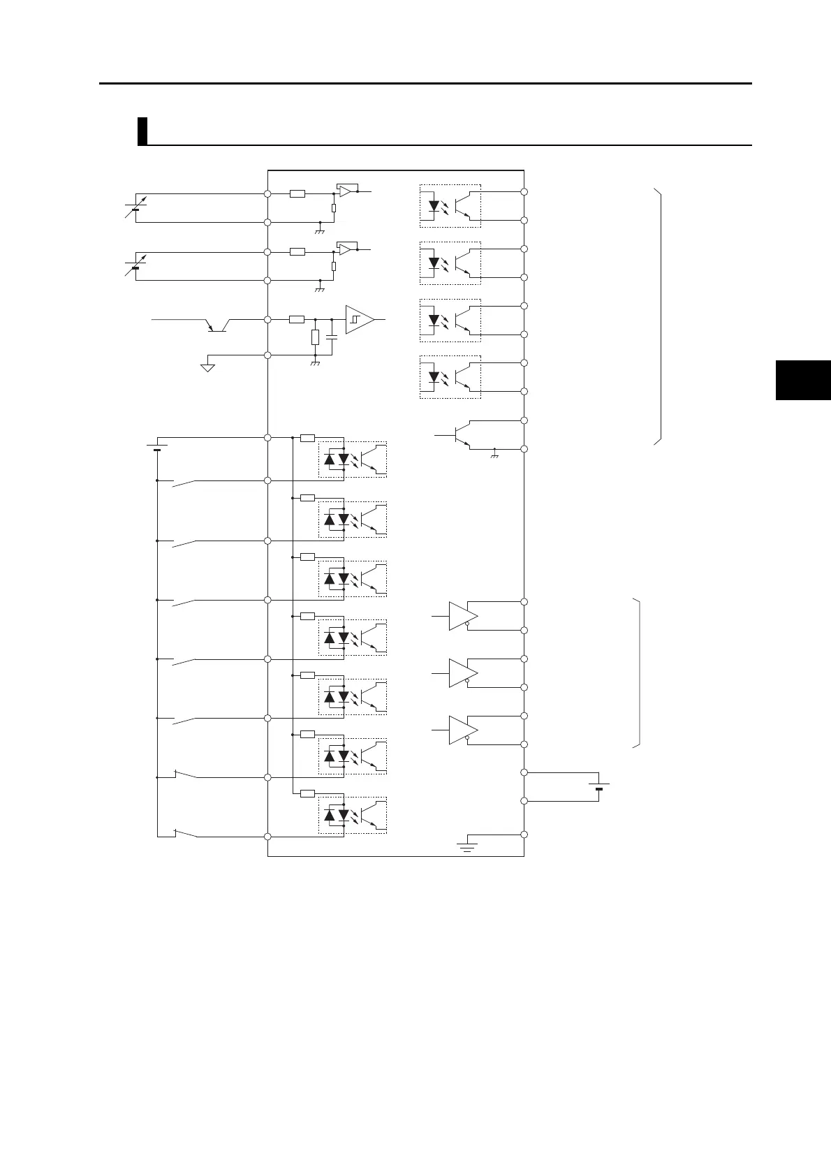
Control I/O Signal Connections and External Signal Processing for Torque Control
*1. A cable equipped with a battery is not required if a backup battery is connected.
Note 1. The inputs of pins 8, 9 and 26 to 33, and outputs of pins 10, 11, 34, 35, 38 and 39, can be changed via parameter
settings.
Note 2. Pins 13, 20, 42 and 43 represent signals which are applicable when an absolute encoder is used.
Note 3. If pins 21, 22, 49, 48, 23, and 24 are used for the encoder output, use pin 25 (ZGND) to wire the ground.
Note 4. It is not necessary to wire input pins that are not being used.
20
100 Ω
4.7 kΩ
1 μF
SEN
SENGND
13
Sensor ON
BAT
BATGND
Backup battery
*1
42
43
Operation
command
BKIR
Brake interlock
Alarm output
BKIRCOM
11
10
READY
READYCOM
ALMCOM
35
34
/ALM 37
36
TGONCOM
TGON
39
38
9
TVSEL
8
RESET
32
31
27
GSEL
26
VZERO
29 RUN
7
+24VIN
Control mode
switching
Alarm reset
Gain switching
Zero speed
designation
12 to 24 VDC
Maximum
service voltage
30 VDC
Maximum
output current:
50 mA DC
NOT
Reverse drive
prohibition
POT
Forward drive
prohibition
ZGND
Z
19
25
Frame ground
FG
Shell
4.7 kΩ
+A 21
−A 22
+B 49
−B 48
+Z 23
−Z 24
Line-driver output
corresponding with
the EIA RS-422A
communications
method
(load resistance
120 Ω min.)
4.7 kΩ
4.7 kΩ
4.7 kΩ
4.7 kΩ
4.7 kΩ
4.7 kΩ
TREF1/VLIM
AGND1
3.83 kΩ
20 kΩ
3.83 kΩ
10 kΩ
TREF2
AGND2
Torque command input
16
17
14
15
Encoder
phase-A output
Encoder
phase-Z output
Encoder
phase-B output
Phase-Z output
(open-collector
output)
Servo ready
completed output
Motor rotation
speed detection
output
Torque command input
or speed limit
 Loading...
