8 Switch Mode Power Supply S82J
Construction and Nomenclature
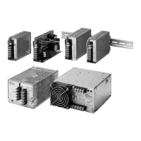
■ Nomenclature
10-/25-/50-/100-/150-W Models
300-W Models
1. DC Output Terminals: Connect the load lines to these
terminals.
2. AC Input Terminals: Connect the input lines to these
terminals.
Note: 1. The fuse is located on the (L) side. It is NOT user
replaceable.
2. For DC input (10-W, 25-W models), use the (L)
terminal as the positive terminal.
3. PE Terminal/Protective earthing terminal: Connect the
ground line to this terminal.
4. Input Voltage Selector Terminals: Short-circuit the
terminals if the input is 100 to 120 VAC and open the
terminals if the input is 200 to 230 VAC
5. Output Indicator (DC ON: Green): Lights while a Direct
Current (DC) output is ON.
6. Output Voltage Adjuster (V.ADJ): It is possible to
increase or decrease the output voltage by 10%.
7. Protection-ON Alarm Indicator (DC ON: Red): The red
indicator will be lit if the overvoltage (for a 300-/600-W
model) or overheat protection (for a 600-W model) circuit
is triggered. This indicator will also be lit when overcurrent
(for a 600-W model) is detected.
8. Parallel/Single Operation Selector: Set the selector to
PARALLEL if the Units are in parallel operation.
600-W Models
5
6
1
3
2
+V
−V
AC (L)
AC (N)
Front Terminals Model
+V
+V
−V
−V
5
6
1
AC (L)
AC (N)
2
4
3
8
7
Side view
1
65 7
8
4
2
3
AC (L)
AC (N)
Side view
−V +V−V +V
 Loading...