S8JX
15
S8JX-G S8JX-P
Common Precautions
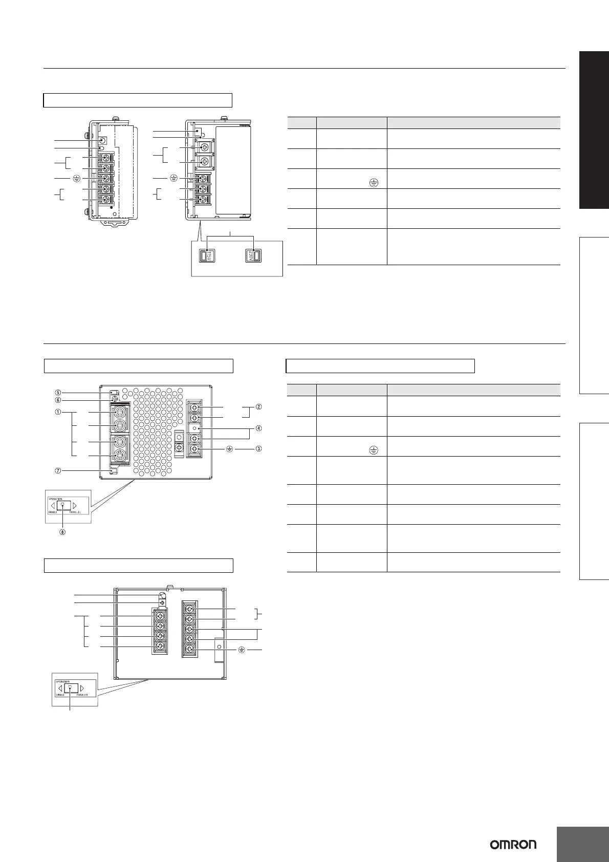
Construction and Nomenclature
Nomenclature
15-/35-/50-/100-/150-W Models
E
D
A
C
B
+V
−V
AC (L)
AC (N)
100 to 120 VAC 200 to 240 VAC
E
F
D
A
C
B
+V
−V
AC (L)
Bottom
AC (N)
*1. The fuse is located on the (L) side. It is NOT user-replaceable. For a DC
power input, connect the low side to the positive (+) terminal.
*2. This is the protective earth terminal specified in the safety standards.
Always ground this terminal.
*3. This item is applicable only to the S8JX-G15005@@.
No. Name Function
1
DC Output
Terminals (−V), (+V)
Connect the load lines to these terminals.
2
AC Input Terminals
(L), (N)
Connect the input lines to these terminals. *1
3
Protective Earth
Terminal (PE) ( )
Connect the ground line to these terminals. *2
4
Output Voltage
Adjuster (V. ADJ)
It is possible to increase or decrease the output
voltage.
5
Output Indicator
(DC ON: Green)
Lights green while a direct current (DC) output is ON.
6
Input voltage switch
*3
Switches the internal circuits according to the input
voltage.
"115V": 100 to 120 VAC
"230V": 200 to 240 VAC
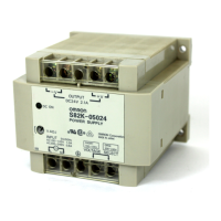
Note: The S8JX-G05024CD is
shown above.
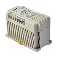
Note: The S8JX-G15005C is shown
above.
+V
+V
−V
−V
AC(L)
AC(N)
Bottom
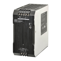
Note: The S8JX-G30005C is shown above.
*1. The fuse is located on the (L) side. It is NOT user-replaceable.
*2. This is the protective earth terminal specified in the safety standards.
Always ground this terminal.
*3. This is not applicable to 24-V and 48-V models.
No. Name Function
1
DC Output
Terminals (+V), (−V)
Connect the load lines to these terminals.
2
AC Input Terminals
(L), (N)
Connect the input lines to these terminals. *1
3
Protective Earth
Terminal (PE) ( )
Connect the ground line to these terminals. *2
4
Input Voltage
Selector Terminals
Short-circuit the terminals if the input is 100 to 120
VAC and open the terminals if the input is 200 to 240
VAC.
5
Output Indicator
(DC ON: Green)
Lights green while a direct current (DC) output is ON.
6
Output Voltage
Adjuster (V. ADJ)
It is possible to increase or decrease the output
voltage.
7
Protection-ON
Alarm Indicator
(ALM: Red)
The red indicator will be lit if the overvoltage or
overheat protection circuit is triggered. This indicator
will also be lit when overload is detected. *3
8
Selector of Parallel
Operation
Set the selector to PARALLEL if the Units are in
parallel operation.
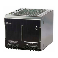
300-W 24V, 48V Model
AC (L)
AC (N)
Bottom
+V
+V
−V
−V
E
F
D
C
A
B
Note: The S8JX-G30024C is shown above.
300-W 5V, 12V Model 300-W Model
 Loading...