8 Switch Mode Power Supply S8VM
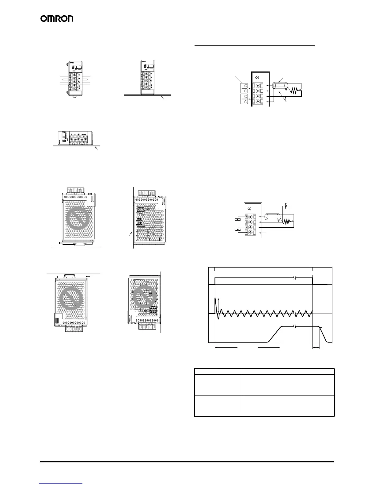
� Mounting
Note: 1. Improper mounting will interfere with heat dissipation and
may occasionally result in deterioration or damage of inter-
nal parts.
Use the product within the derating curve for the mounting
direction that is used.
2. Use the metal plate as the mounting panel (*1).
3. Install the Power Supply so that the air flow circulates
around the Power Supply, as the Power Supply is designed
to radiate heat by means of natural air flow.
4. Mounting screw tightening torque
(recommended value: 0.49 N·m)
� Remote Sensing Function
(S8VM-100@@@@/150@@@@ only)
This function compensates a voltage drop on the load lines.
To use this function, connect after removing the two short bars of the
remote sensing terminal.
Note: 1. Use a 2-conductor shielded cable as a connection wire (*1).
2. Use as thick a wire as possible since high voltage drops on
the load lines (*2) may activate the overvoltage protection
function.
3. Use when the voltage drop is 0.3 V or lower.
4. When the +S and
−S terminals are opened with the short bar
removed, the overvoltage protection function is activated
and the output voltage will be cut off.
5. If the load line is too long, use an electrolytic capacitor in the
following 3 locations:
1) Across the load terminals
2) Between the +S terminal and + terminal
3) Between the
−S terminal and − terminal
Select the capacity of the connected capacitor from be-
tween several tens to several hundreds of
µF as a guide,
and then determine the capacity when actually connecting
the capacitor between terminals as shown below.
� Inrush Current, Start Up Time,
Output Hold Time
� Reference Values
*1
*1
*1
Standard mounting
(DIN Rail mounting bracket type)
Standard mounting
(Front-mounting type)
Horizontal mounting
(Front-mounting type)
Correct
Correct
Correct
Face-up mounting
(DIN Rail mounting bracket type)
Face-up mounting
(Front-mounting type)
Incorrect
Correct
Face-down mounting
(DIN Rail mounting bracket type)
Face-down mounting
(Front-mounting type)
Incorrect
Incorrect
Item Value Definition
Reliability
(MTBF)
135,000 hrs
min.
MTBF stands for Mean Time Between Failures, which
is calculated according to the probability of accidental
device failures, and indicates the reliability of a device.
Therefore, it does not necessarily represent the life of
the product.
Life
expectancy
10 yrs. min. The life expectancy indicates average operating hours
under the ambient temperature of 40
° C and a load rate
of 50%.
Normally this is determined by the life expectancy of
the built-in aluminum electrolytic capacitor.
DC ON
V.ADJ
+
S
+ V
−V
−S
*
1
*
2
Short bar
DC ON
V.ADJ
+
S
+ V
−V
−S
+
+
+
Start up time
Hold time
Inrush current on input application
90%
95%
Input ON
Input OFF
AC input
voltage
AC input
current
Output
voltage