SmartStep 2 servo system 15
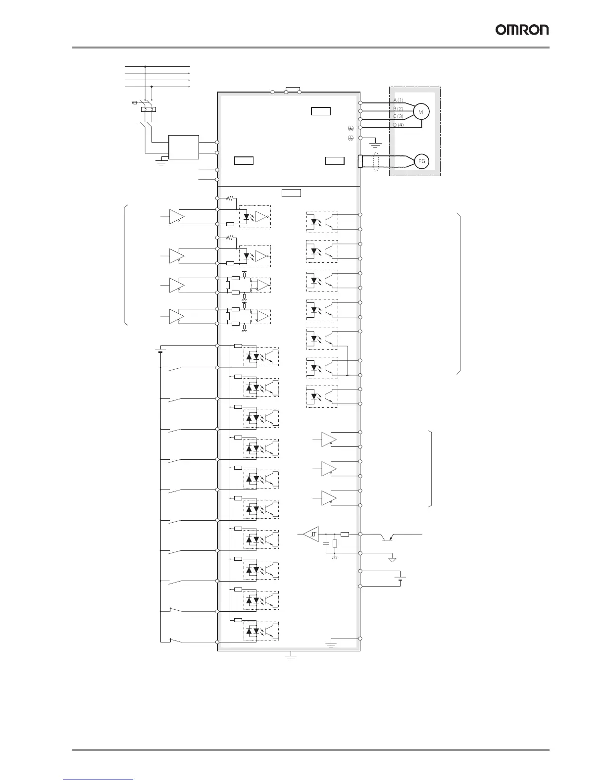
*1 B3-B2 are short-circuited. If the internal regenerative resistor is insufficient, remove the wire between B2 and B3 and connect an external regen-
erative resistor between B1 and B2.
*2 Use only when an absolute encoder. If a backup battery is connected, an encoder cable with a battery is not required.
*3 The default values are ZSP (zero-speed detection) for OUTM1 and T-LIMIT (at torque limit) for OUTM2.
SMARTSTEP2
Servo drive
(750W)
Optical encoder
Servo motor
B3
B2
U
V
W
B1
L1
L3
L1C
L2C
Noise filter
Single-Phase
200 to 230 VAC
Contactor
L1
L2
L3
N
Thermal switch
CN1
*1
3 kΩ
110 Ω
43 kΩ
3k Ω
220 Ω
5
2
6
Servo ON
44
45
+CW
-CW
+CCW
-CCW
+CWLD
-CWLD
Reverse pulse
Forward pulse
BKIR
Alarm output
BKIRCOM
11
10
READY
READYCOM
ALMCOM
35
34
/ALM37
36
INPCOM
INP39
38
32TVSEL
31RESET
30ECRST
28GESEL
27
GSEL
26
DFSEL
29RUN
7+24 VIN
Control mode
switching
Alarm reset
Deviation counter reset
Electronic gear
switching
Gain switching
Vibration filter
switching
12 to 24 VDC
External power supply 12 to 24 VDC
Maxim
um
service voltage: 30 VDC
Maximum
output current: 50 mADC
Reverse pulse
46
47
110 Ω
43 kΩ
33IPG
Pulse prohibition
500 kpps max.
2 Mpps max.
8NOT
Reverse run
prohibited
9POT
Forward run
prohibited
OUTM1
General-purpose output 1
12
50
4.7 k
Ω
4.7 k
Ω
4.7 k
Ω
4.7 kΩ
43 kΩ
3
kΩ
+CCWLD
-CCWLD
Forward pulse
+A21
-A22
+B49
-B48
+Z23
-Z24
Line-driver output corresponding
with the EIA RS-422A communications
method (load resistance 120 W min.)
220 Ω
3
1
4
43 kΩ
3k Ω
4.7 k
Ω
4.7 k
Ω
4.7 k
Ω
4.7 kΩ
4.7 k
Ω
4.7 kΩ
+24 VCW
2.2 kΩ
+24 VCCW
2.2 kΩ
20
100Ω
4.7 kΩ
1 µF
SEN
SENGND
13
Sensor ON
BAT
BATGND
Backup battery
(3.6 V)
42
43
Position reference
Shell
*2
CNB
CNA
CN2
Servo ready output
Positioning completed output
COM-
OUTM2
40
41
Brake release signal output
19
25 ZCOM
Z
Phase-Z output
(open collector output)
Encoder phase-A output
Encoder phase-B output
Encoder phase-Z output
General-purpose output 2
*3
*3