21
Note As the operating current is extremely small, use shielded cables for connec-
tions and/or keep wiring as distant as possible from power lines. Further-
more, keep all connections are as short as possible, and not more than 10
meters in length.
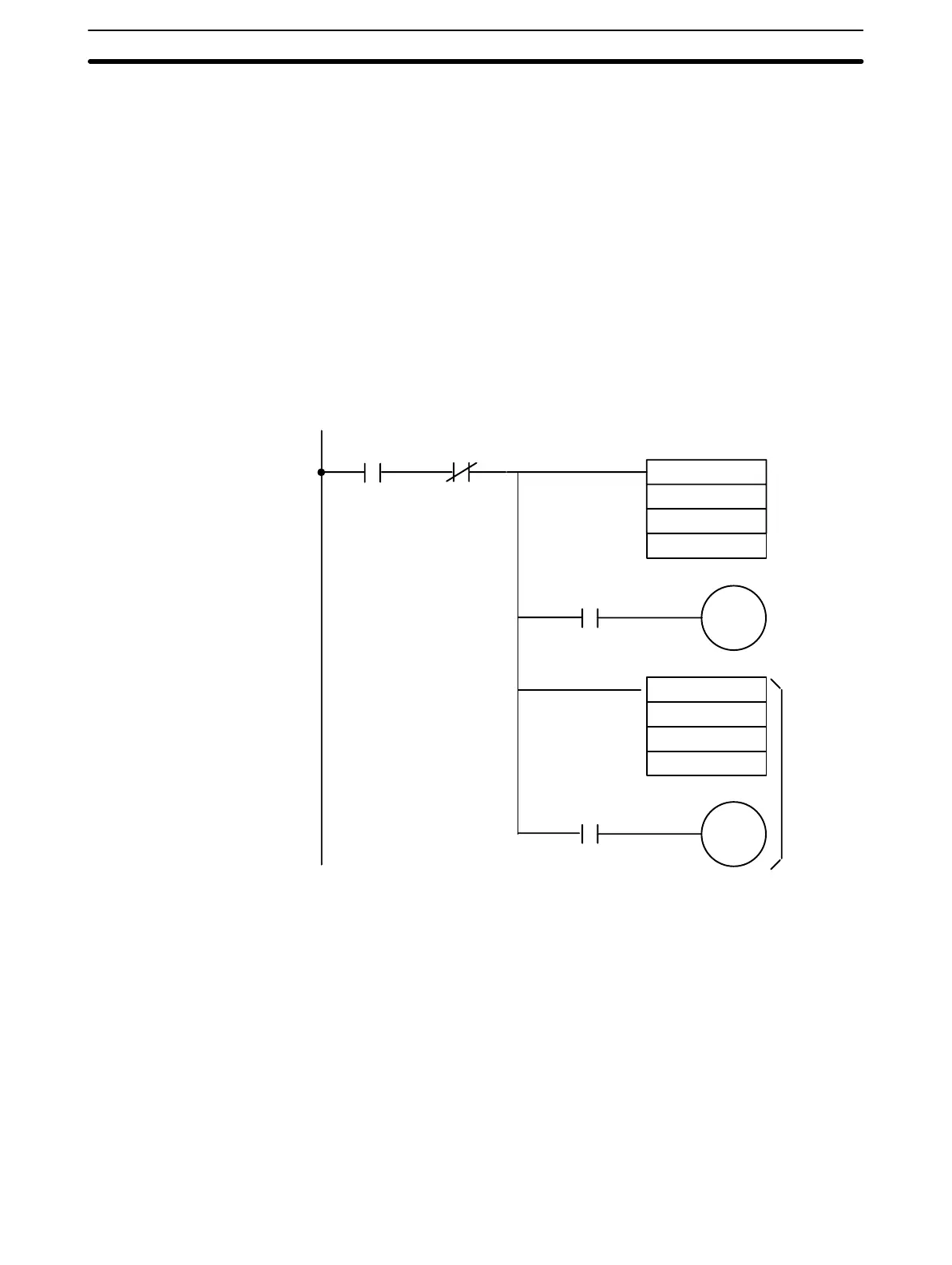
Program Masks the signal bit (10115) corresponding to the temperature data (word
101) of Input 1, and outputs to word 120 of the High-Density and Multiplex
I/O Unit.
When the temperature is negative (when bit 10115 is ON), word 121 bit 15
(of the High-Density and Multiplex I/O Unit) turns ON. A negative sign is then
shown on the display.
The above also applies to temperature data (word 102) of Input 2.
25313
(Always ON)
12115
ANDW (34)
#7FFF
101
120
10507
(Data invalid)
10115
ANDW (34)
#7FFF
102
122
10215
12315
Checks data validity
Signal bit of Input 1 data
Signal bit of Input 1 data
Note The Display Unit displays numerical data only if each digit is in BCD. Other-
wise, the display remains blank. The display range is -9,999,999 to
9,999,999. Refer to each manual for more details on the Transistor Output
Unit C200H-OD215 and Display Unit.
Input Data Conversion The temperature data to be input is converted to 4-digit BCD in the Master
and then output to the conversion words, n+1 through n+4. This conversion
data has an error tolerance of 10 beyond the standard temperature range.
When the conversion result is not within the tolerance range, the data of
words n+1 through n+4 becomes FFFF. If the input temperature is negative,
bit 15 for each of the conversion words (n+1 through n+4) turns ON and the
data becomes 8XXX.
Temperature Data Display Section 4-2