105
Wiring Section 3-3
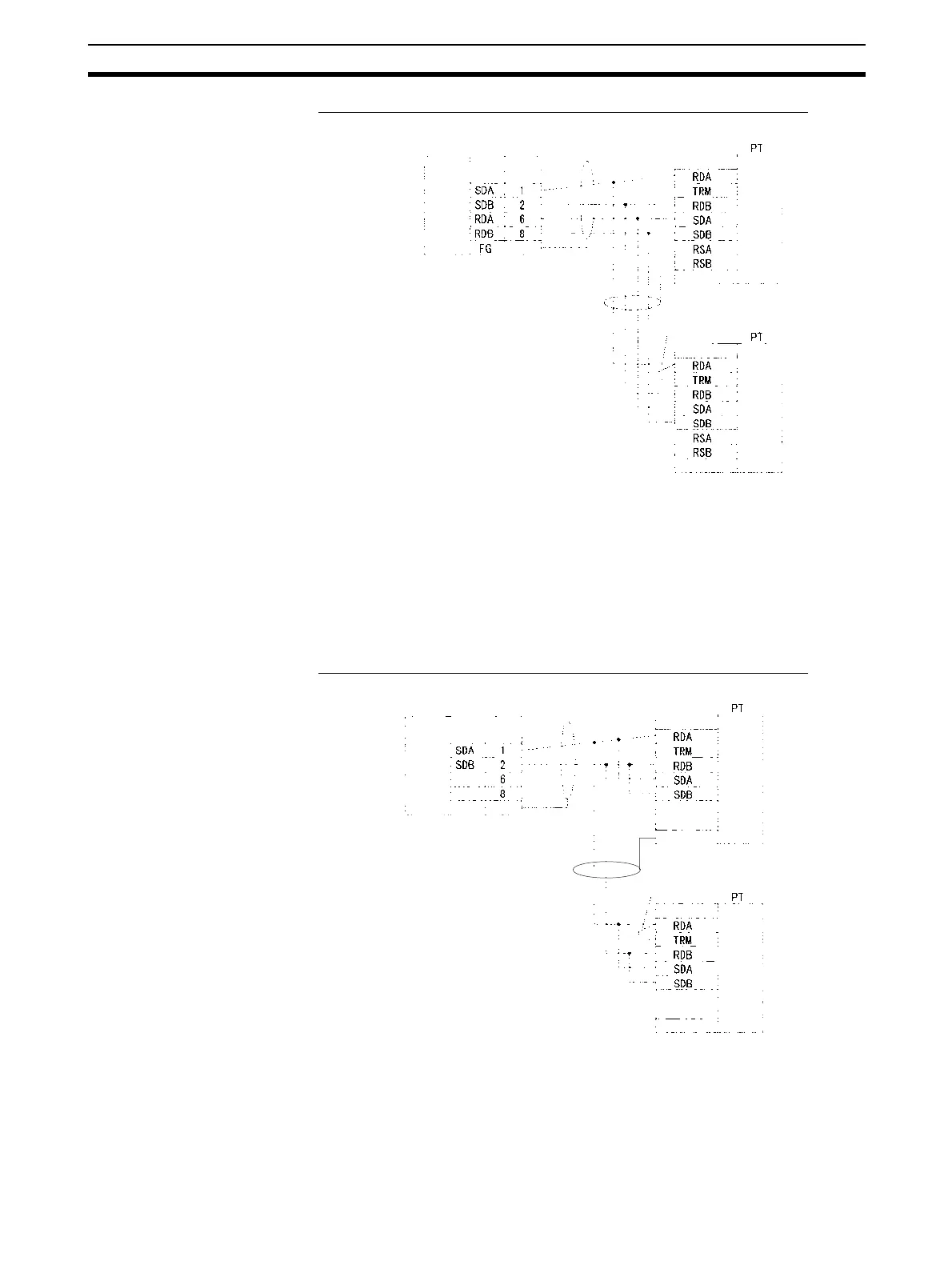
1:N, 4-wire Connections from RS-422A/485 to RS-422A/485 Ports
Communications Mode: 1:N NT Link
Note 1. Serial Communications Board/Unit settings:
Terminating resistance ON, 4-wire.
2. The terminating resistant setting shown above is an example for the
NT631/NT631C. The setting method varies with the PT. Refer to the man-
ual for you PT for details.
1:N, 2-wire Connections from RS-422A/485 to RS-422A/485 Ports
Communications Mode: 1:N NT Link
Note 1. Serial Communications Board/Unit settings:
Terminating resistance ON, 2-wire.
Serial Communications
Board/Unit
Pin
Signal
Signal
Terminal block or D-sub
connector
RS-422A
/485 In-
terface
Hood
D-sub, 9-pin
connector (male)
Short bar
Terminal block or D-sub
connector
RS-422A
/485 In-
terface
RS-422A
/485 In-
terface
FG
FG
Signal
(See note 2.)
Serial Communications Board/Unit
Pin
Signal
Signal
Terminal block or D-sub connecto
FG
Hood
D-sub, 9-pin
connector (male)
RS-422A
/485 In-
terface
Short bar
Signal
RS-422A
/485 In-
terface
Terminal block or D-sub connector
FG
RS-422A
/485 In-
terface
(See note 2.)
 Loading...


