205
Auxiliary Area and CIO Area in Serial Gateway Mode Section 6-3
Serial Communications Boards (CS Series Only)
Serial Communications Units (CS/CJ Series)
n = A620 + unit number
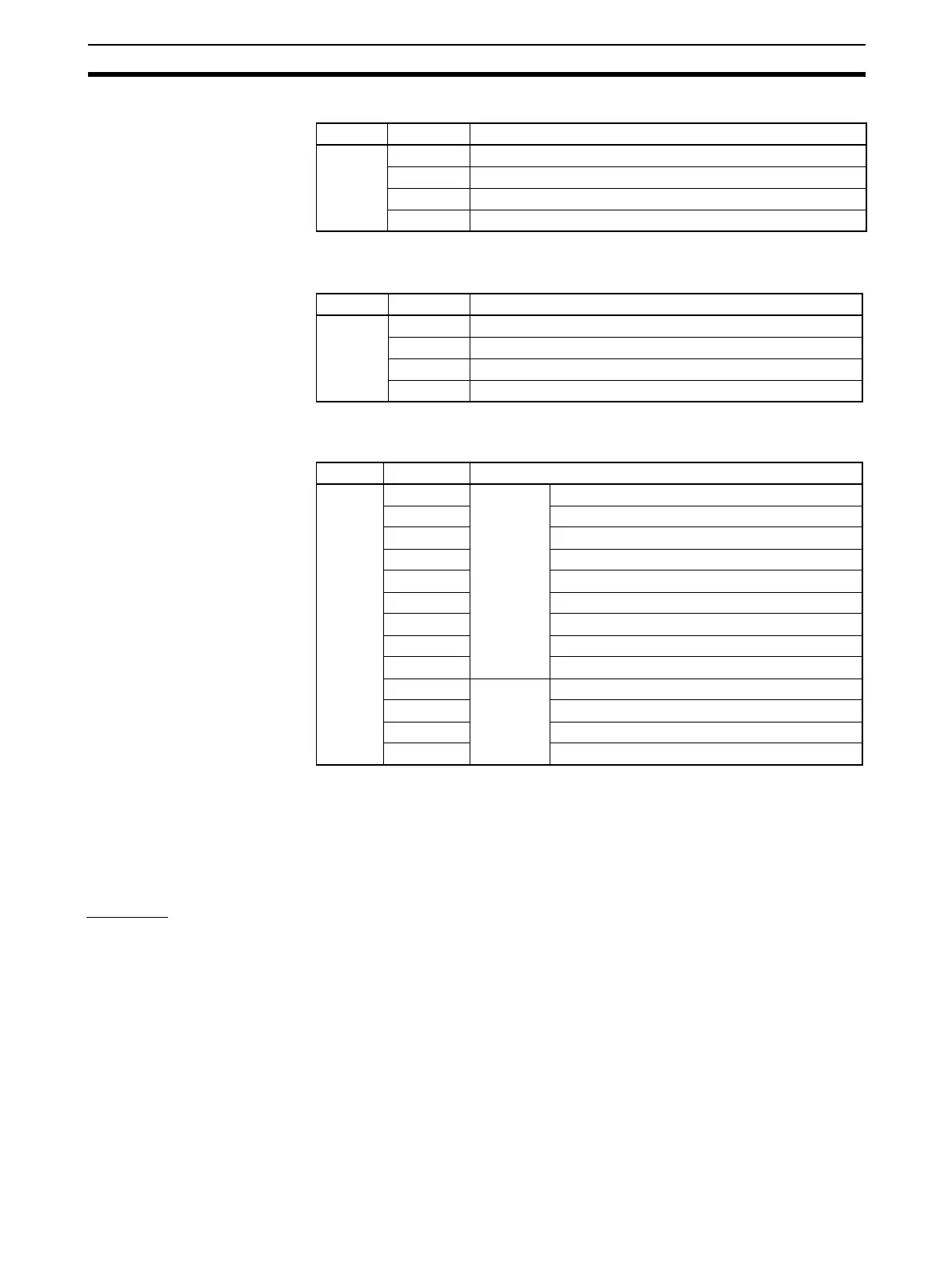
Inner Board Error Details (CS-series Serial Communications Boards Only)
A424 contains error information for the Serial Communications Board.
Note (1) If any of bits 05 to 11 turn ON (1), A40208 (Inner Board Error Flag) (non-
fatal error) will turn ON (1).
(2) If either bit 00 or 01 turns ON (1), A40112 (Inner Board Fatal Error Flag)
will turn ON (1).
For details on errors, refer to Section 11
Troubleshooting and Maintenance.
CIO Area
Words in the CIO Area are allocated as Software Switches, which are manip-
ulated from the CPU Unit to control the operation of the Serial Communica-
tions Board or Unit, and for a Status Area, which contains status and error
information for the Serial Communications Board or Unit.
Serial Communications Boards (CS Series Only)
Words CIO 1900 to CIO 1999 in the Inner Board Area are allocated for the
Serial Communications Board. In Serial Gateway Mode, only the following
words are used as the CIO Area. No other words are used.
Word Bit Setting
A636 03 to 15 Reserved
02 1: Port 2 Settings Change Bit
01 1: Port 1 Settings Change Bit
00 Reserved
Word Bit Setting
n 03 to 15 Reserved
02 1: Port 2 Settings Change Bit
01 1: Port 1 Settings Change Bit
00 Reserved
Word Bit Setting
A424 12 to 15 Non-fatal
error (See
note 1.)
Reserved
11 1: Error log EEPROM error; 0: Normal
10 Not used
09 Not used
08 1: Setup error; 0: Normal
07 1: Routing table error; 0: Normal
06 Reserved
05 1: Cyclic monitoring error; 0: Normal
04 Reserved
03 Fatal error
(See note
2.)
Reserved
02 Reserved
01 1: Inner bus error; 0: Normal
00 1: Inner Board watchdog timer error; 0: Normal
 Loading...


