270
Auxiliary Area and CIO Area Allocations Section 8-3
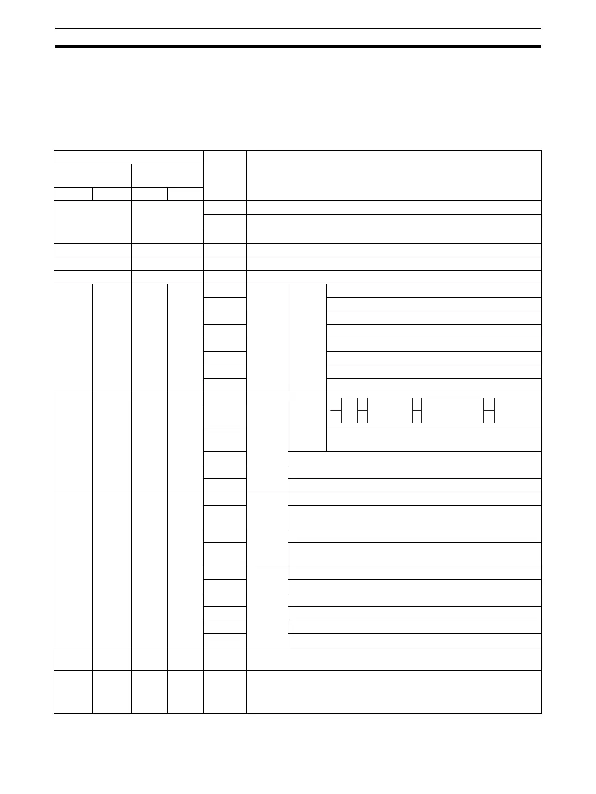
8-3-3 Status Area Contents
The Status Area is used to input status information from Serial Communica-
tions Board or Unit to the CPU Unit. The Status Area is where the Serial Com-
munications Board or Unit set communications status, the transmission
control signal status, and the transmission error status.
n = CIO 1500 + 25
× unit number
Words Bit Contents
Boards
(CS Series only)
Units
(CS/CJ Series)
Port 1 Port 2 Port 1 Port 2
CIO 1901 n + 1 02 to 15 Reserved
01
1: Error log data error 0: Error log data normal
00
1: Protocol data error 0: Protocol data normal
CIO 1902 n + 2 00 to 15 Reserved
CIO 1903 n + 3 00 to 15 Reserved
CIO 1904 n + 4 00 to 15 Reserved
CIO
1905
CIO
1915
n + 5 n + 15 12 to 15 Port set-
ting
status
Setup
Area
Serial communications mode: Always 2 Hex
08 to 11 Baud rate: 0 to 9 Hex, A Hex ()
05 to 07 Reserved
04 Start bit: Always 0 Hex
03 Data length: Always 1 Hex
02 Stop bit: Always 1 Hex
01 Parity, Yes/No: Always 0 Hex
00 Parity, Even/Odd: Always 1 Hex
CIO
1906
CIO
1916
n + 6 n + 16 15 Port set-
ting
status
Hard-
ware
settings
14
13 0: Terminating resistance OFF
1: Terminating resistance ON
02 to 12 Reserved
01 1: Setup error 0: Setup normal
00 1: Port operating 0: Port stopped
CIO
1907
CIO
1917
n + 7 n + 17 11 to 15 Commu-
nica-
tions
status
Reserved
10 1: Remote Unit receive busy (flow control)
0: Remote Unit receive wait (Always 0 Hex)
09 Reserved
08 1: Local Unit receive busy (flow control)
0: Local Unit receive wait (Always 0 Hex)
07 Trans-
mission
control
signal
status
ER signal
06 DTR signal
05 Reserved
04 CTS signal
03 RTS signal
00 to 02 Reserved
CIO
1908
CIO
1918
n + 8 n + 18 00 to15 Reserved
CIO
1909 to
CIO
1914
CIO
1919 to
CIO
1924
n + 9 to
n + 14
n + 19
to
n + 24
15 to 00 Protocol status
0 No 0 RS-232C 1 RS-422A/485 1 Reser ved
0 1 0 1
 Loading...


