660
3Z4L Laser Micrometer Protocol Appendix N
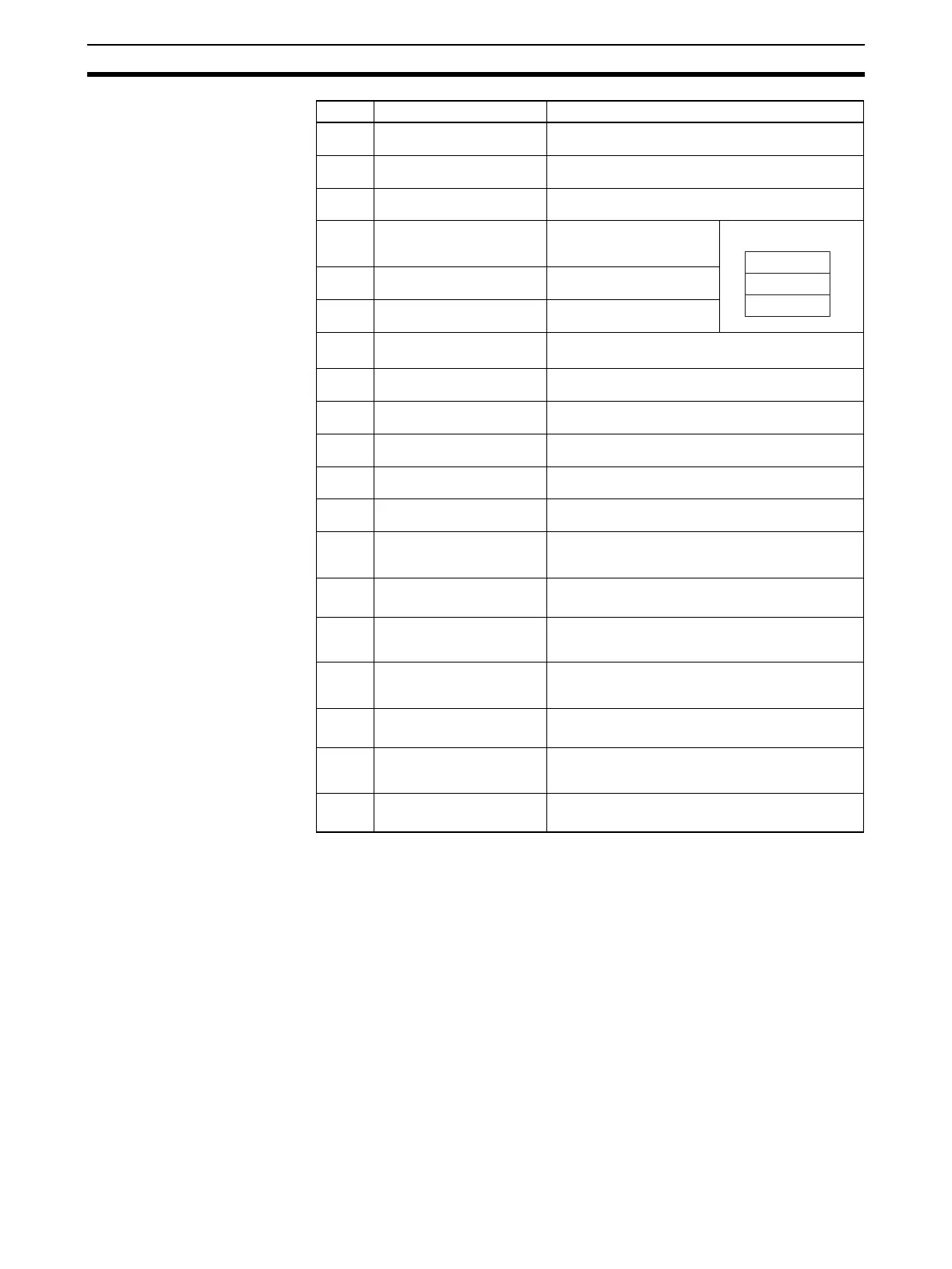
Receive Data Word Allocation (4th Operand of PMCR(260))
None.
Note 1. The following settings must be made together with this sequence; they cannot be set separately.
Lower limit, upper limit
Reference value, data output timer
Data output conditions, scheduled print timer
2. The limit value and reference value can be set to 3 digits for the integer portion and to 4 digits for the
decimal portion.
Offset Contents (data format) Data
+0 Number of send data words
(4 digits Hex)
0019 (0025 decimal) (fixed)
+1 Segment number
(1 digit BCD)
1 to 5
+2 Measurement interval num-
ber (1 digit BCD)
1 to 7
+3 Lower limit value (Decimal
portion)
(4 digits BCD)
0000 to 9999
+4 Lower limit value (integer
portion) (3 digits BCD)
000 to 999
+5 Lower limit value (Sign)
(ASCII 1 character)
If +: 20 (‘ ’)
If –: 2D (‘–’)
+6 to +8 Upper limit value Same as lower limit value
+9 to
+11
Reference value Same as lower limit value
+12 Analog output scale number
(1 digit BCD)
0 to 3
+13 to
+15
Unused
+16 Data output conditions
(1 digit BCD)
0 to 6
+17 Data output timer value
(3 digits BCD)
000 to 999
+18 Number of seconds for latch
timer
(2 digits BCD)
00 to 99
+19 Yes/No for segment setting
(1 digit BCD)
Set: 1(SG)
Don’t set: 0
+20 Yes/No for measurement
interval number setting
(1 digit BCD)
Set: 1(M)
Don’t set: 0
+21 Yes/No for upper/lower limit
value setting
(1 digit BCD)
Set: 1(LL, LH)
Don’t set: 0
+22 Yes/No for reference setting
(1 digit BCD)
Set: 1(REF, SCL)
Don’t set: 0
+23 Yes/No for data output condi-
tion setting
(1 digit BCD)
Set: 1(PR, PRT)
Don’t set: 0
+24 Yes/No for latch timer setting
(1 digit BCD)
Set: 1(RLT)
Don’t set: 0
Example –123.4567
4 5 6 7
0 1 2 3
2 D 0 0
+3
+4
+5
 Loading...


