63
Component Names and Functions Section 2-1
Error Information. Refer to Inner Board Error Information under 2-3-3 Related
Auxiliary Area Bits.
For actions required when an error occurs, refer to Section 11 Troubleshooting
and Maintenance.
RS-232C Ports
Note 1. High-speed NT link is only available with Serial Communications Boards/
Units manufactured on or after December 20th, 1999. With earlier models,
only standard NT link is available.
2. The maximum cable length for RS-232C is 15 m. The RS-232C standard,
however, does not cover baud rates above 19.2 Kbps. Refer to the manual
for the device being connected to confirm support.
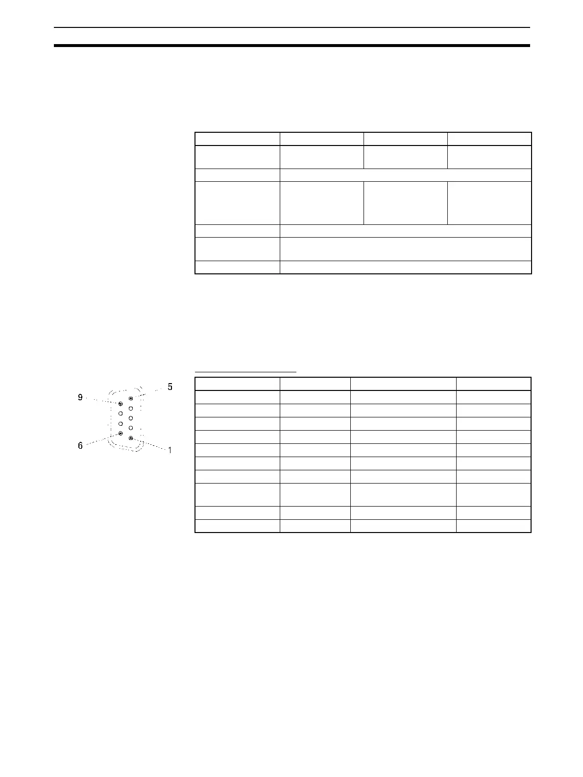
Connector Pin Layout
Note 1. Pin No. 1 and the shell are connected to the ground terminal (GR) of the
Power Supply Unit inside of the Serial Communications Board. Therefore,
the cable shield can be grounded by grounding the GR of the Power Sup-
ply Unit.
2. The status of the RTS (RS), CTS (CS), DSR (DR), and DTR (ER) signals
can be monitored in the words allocated in the CIO Area. For details, refer
to 2-3 I/O Memory Allocations.
3. Pin 6 (5 V) is required when the NT-AL001-E Link Adapter is connected.
For details on connection methods, refer to 3-3 Wiring.
4. The DSR signal is used to monitor the signal cable. It can also be used as
a CD (carrier detect) signal. (The DSR signal does not affect system oper-
ation, and is available for use by the user.)
Protocol Host Link Protocol macro 1:N NT Links
Communications
method
Full-duplex Full-duplex or half-
duplex
Half-duplex
Synchronization Start-stop synchronization (asynchronous)
Baud rate 1,200/2,400/4,800/
9,600/19,200/
38,400/57,600/
115,200 bps
1,200/2,400/4,800/
9,600/19,200/
38,400 bps
Standard NT link or
high-speed NT link
Connections 1:1 (1:N is possible using Link Adapters)
Transmission
distance
15 m max. (see note 2)
Interface Complies with EIA RS-232C
Pin No. Abbreviation Signal name I/O
1 (see note 1) FG Shield ---
2 SD Send data Output
3 RD Receive data Input
4 (see note 2) RTS (RS) Request to send Output
5 (see note 2) CTS (CS) Clear to send Input
6 (see note 3) 5V Power supply ---
7 (see note 2) DSR (DR) Data set ready Input
8 (see note 2) DTR (ER) Data terminal ready (see
note 4)
Output
9 SG Signal ground ---
Shell (see note 1) FG Shield ---
 Loading...


