Analog Inputs Are Made Simple.
An analog adjustment and an external analog
setting input connector are provided.
Analog Adjustment
CP1W-ME05M
Memory Cassette
PLC program design
Memory Cassette
Production site
Production site
System
development
That’s a
memory
error.
Example display: A memory error occurs in the
UM (error code 80F1, error details 0001).
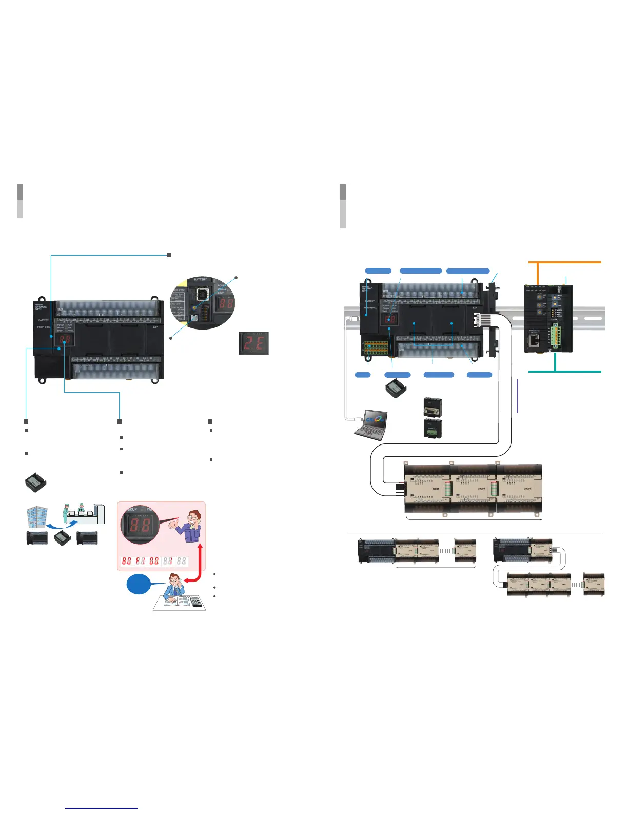
Handy Built-in Functions
Make Maintenance Easier.
DeviceNet
CompoBus/S
Serial Communications
Ethernet
Controller Link
Over-the-counter
USB cable
Analog I/O
(CP1H-XA
CPU Units
Only)
Peripheral USB port 7-segment display Built-in Input Terminal Block
Built-in Output Terminal
Block
RS-232C or RS-422A/485
Option Boards
Built-in Analog
I/O Terminal Block
Memory Cassette
High-speed Counters for Four Axes
Serial Communications Four Pulse Outputs
Saving the Program
Analog I/O
Status and Operation Monitoring
Peripheral Devices
Only one I/O Connecting Cable can be used.
Expansion I/O Units can also be wired below by using
CP1W-CN811 I/O Connecting Cable.
7 Units max.
7 Units max.
CP1W-CN811
I/O Connecting
Cable: 80 cm
Memory Cassette
The analog adjustment
has a resolution of 256.
Values are entered in
A642 and can be used
in the ladder program.
When the value is
changed, it is displayed
(0 to FF) for three
seconds on the 7-
segment display.
External Analog Setting
Input Connector
This connector has a resolution of
256 and is used for an analog
input set to 0 to 10 V. Each CP1H
CPU Unit has one of these
connectors built in. (The built-in
analog I/O for CP1H-XA CPU Units
is separate.)
A device, such as a
potentiometer, can be connected
to enable direct manual operation
and control from a control panel.
The maximum cable length is 3
meters. A connecting cable (1 m)
is included with the CPU Unit.
Data, such as programs and initial
memory values, can be stored on a
Memory Cassette (optional) and
copied to other systems.
The Memory Cassette can also be
used when installing new versions
of application programs.
Status Displayed on
7-segment Display
The 7-segment display provides
two display digits.
In addition to displaying error codes
for errors detected by the PLC,
codes can be displayed on the
display from the ladder program.
The 7-segment display is useful for
maintenance as well, allowing
problems that arise during system
operation to be grasped without
using any Support Software.
Battery-free Operation
The values in the DM Area
(32 Kwords) are saved in the
CPU Unit’s built-in flash
memory as initial values,
and can be read at startup.
Battery-free operation is
also possible when saving
production data and
machine parameters in the
DM Area, turning OFF the
power, and using then same
data again for the next
production run.
A battery is required for the clock
function and to retain the status of
HR Area bits and counter values.
A battery is provided as a standard
feature with the CPU Unit.
The user program (ladder
program) is stored in built-in flash
memory, so no battery is required
to back it up.
Communications Expansion to
Higher and Lower Network
Layers, System Expansion, and
Information Management Are
Made Easy.
Use a CP1W-CN811 I/O
Connecting Cable when using
CPM1A Expansion I/O Units
with a CJ Unit Adapter.
A maximum of seven CPM1A Expansion I/O Units can be
connected. For details on Unit restrictions, refer to page
16.
Up to 320 I/O points can
be obtained by
connecting seven
Expansion I/O Units.
Note: