Appendices
A - 14
NX-series Communications Interface Units User’s Manual (W540)
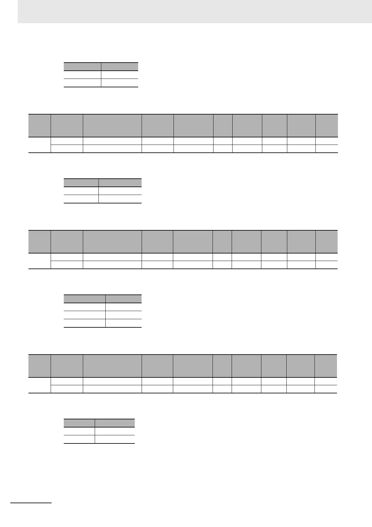
• The following table gives the meanings of the set values for the Ch1 Signal Wire.
• The following table gives the meanings of the set values for the Ch1 Data Bit Length.
• The following table gives the meanings of the set values for the Ch1 Parity.
• The following table gives the meanings of th
e set values of the Ch1 Stop Bits.
Set value Description
0 2-wire
1 4-wire
Index
(hex)
Subindex
(hex)
Object name Default Data range Unit
Data
type
Access
I/O allo-
cation
Data
attri-
bute
5003 --- Data Bit Length --- --- --- --- --- --- ---
01 Ch1 Data Bit Length 0 0 or 1 --- USINT RW No Y
Set value Description
0 7 bits
1 8 bits
Index
(hex)
Subindex
(hex)
Object name Default Data range Unit
Data
type
Access
I/O allo-
cation
Data
attri-
bute
5004 --- Parity --- --- --- --- --- --- ---
01 Ch1 Parity 1 0 to 2 --- USINT RW No Y
Set value Description
0 None
1 Even
2 Odd
Index
(hex)
Subindex
(hex)
Object name Default Data range Unit
Data
type
Access
I/O allo-
cation
Data
attri-
bute
5005 --- Stop Bits --- --- --- --- --- --- ---
01 Ch1 Stop Bits 0 0 or 1 --- USINT RW No Y
Set value Description
0 2 bits
1 1 bit