WL-N/WLG
General-purpose Switches
Environment-resistant Switches
Spatter-prevention Switches
Long-life Switches Accessories Safety Precautions
87
Using the Switches
Item Applicable models and Actuators Details
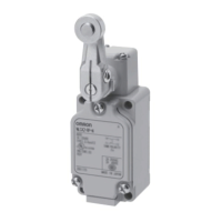
Changing the Installation Position of the
Actuator
By loosening the Allen-head bolt on the ac-
tuator lever, the position of the actuator can
be set anywhere within the 360°.
With Operation Indicator-equipped Switch-
es, the actuator lever comes in contact with
the top of the indicator cover, so use caution
when rotating and setting the lever. When
the lever only moves forwards and back-
wards, it will not contact the lamp cover.
(This does not apply to Long-life Models.)
Roller lever:
(WLCA2-N, WLCA2-2-N, WLCA2-2N-N,
WLG2, WLCA2-7-N, WLCA2-8-N,
WLGCA2, WLMCA2-N, WLMG2,
WLMGCA2)
Adjustable roller lever
(WLCA12-N, WLCA12-2-N,
WLCA12-2N-N, WLG12)
Adjustable rod lever
(WLCL-N, WLCL-2-N, WLCL-2N-N,
WLGL, WLCAL4-N, WLCAL5-N)
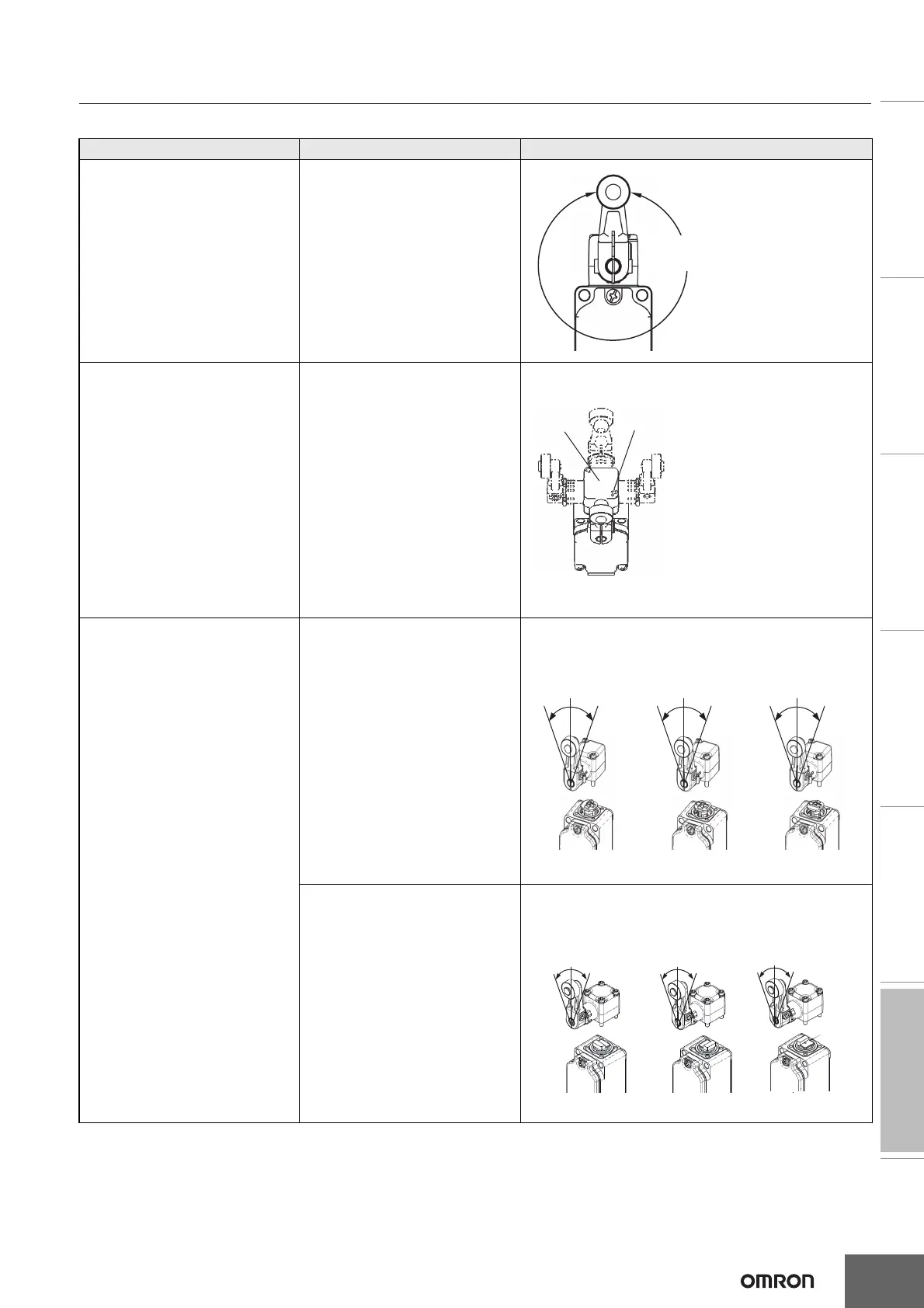
Changing the Orientation of the Head
By removing the head screws (two or four
screws), mounting in any of four orientations
is possible. Be sure to change the plunger
for internal operations at the same time.
The roller plunger can be set in either of two
positions at 90°.
Roller lever:
(WLCA2-N, WLCA2-2-N, WLCA2-2N-N,
WLG2, WLCA2-7-N, WLCA2-8-N,
WLGCA2, WLMCA2-N, WLMG2,
WLMGCA2)
Adjustable roller lever
(WLCA12-N, WLCA12-2-N,
WLCA12-2N-N, WLG12)
Adjustable rod lever
(WLCL-N, WLCL-2-N, WLCL-2N-N,
WLGL, WLCAL4-N, WLCAL5-N)
Horizontal plunger
(WLSD@-N)
Top-roller plunger
(WLD2-N)
Sealed top-roller plunger
(WLD28-N)
Fork lock lever (WLCA32-4@-N)
Note: Does not include -RP60 Series or
-141 Series
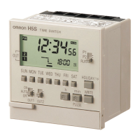
Changing the Operating Direction
By removing the Head on models which can
operate on one-side only, and then changing
the direction of the operational plunger, one
of three operating directions can be select-
ed.
The tightening torque for the screws on the
Head is 0.78 to 0.88 N·m.
Roller lever:
(WLCA2-N, WLCA2-2-N, WLCA2-2N-N,
WLCA2-7-N, WLCA2-8-N, WLMCA2-N)
Adjustable roller lever
(WLCA12-N, WLCA12-2-N,
WLCA12-2N-N)
Adjustable rod lever
(WLCL-N, WLCL-2-N, WLCL-2N-N,
WLCAL4-N, WLCAL5-N)
Roller lever:
(WLGCA2, WLMGCA2)
Loosen the Allen-head bolt, set
the actuator's position and then
tighten the bolt again.
Head
Loosen the screws.
Operating Operating Operating
Not operating
Operating Not operating
Operation in both
directions
Clockwise oper
ation Counterclockwise
operation
The output of the Switch will be
changed, regardless of which
direction the lever is pushed.
One-side Operation for General Models
The output of the Switch will
only be changed when the lever
is pushed in one direction.
Operating Operating
Operation in both
directions
OperatingNot operating
Clockwise operation
Operating Not operating
Counterclockwise
operation
One-side Operation for High-precision Switches
The output of the Switch will be
changed, regardless of which
direction the lever is pushed.
The output of the Switch will
only be changed when the lever
is pushed in one direction.