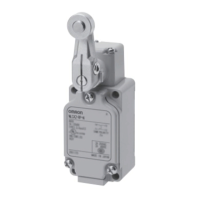
WL-N/WLG
34
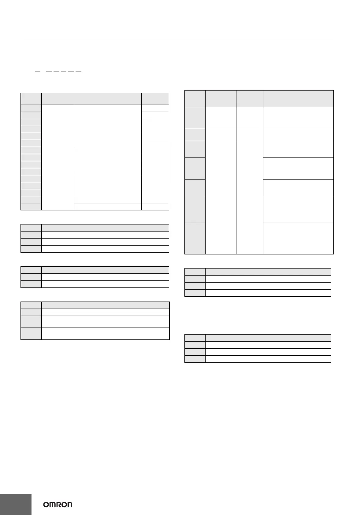
Model Number Structure
Model Number Legend (Not all combinations are possible. Ask your OMRON representative for details.)
Basic models
(1) Actuator and Property Specifications
(2) Environment-resistant Specifications
(3) Built-in Switch Specifications
(4) Temperature Specifications
* (2) Environment-resistant Specifications Cannot be combined with
symbols RP or P1.
(5) Wiring and Built-in Switch Specifications
(6) Indicator Specifications
* (2) Environment-resistant Specifications Cannot be combined with
symbols RP or P1.
(4) Temperature Specifications Cannot be combined with symbols
TH or TC.
(7) Lamp Wiring
WL@ - @@@@@@-N
(1) (2) (3) (4) (5) (6) (7)
Code Actuator
Pretravel
(PT)
CA2
Roller lever
Roller lever: (R38 mm)
15±5°
CA2-2 25±5°
CA2-2N 20° max.
CA12
Adjustable Roller Lever
(R25 to 89 mm)
15±5°
CA12-2 25±5°
CA12-2N
20° max.
D28
Plunger
Actuators
Sealed top-roller plunger
1.7 mm max.
D2 Top-roller plunger
1.7 mm max.
SD Horizontal plunger
2.8 mm max.
SD2 Horizontal-roller plunger
2.8 mm max.
CL
Flexible Rod
Actuators
Adjustable rod lever
(25 to 140mm)
15±5°
CL-2 25±5°
CL-2N 20° max.
NJ Coil spring (6.5 dia.) 20±10mm
NJ-2 Flexible rod: Resin rod (8 dia.) 40±20mm
Code Specifications
None Standard built-in switch
RP Corrosion-resistant type
P1 Weather-resistant type
Code Specifications
None Standard built-in switch
55 Airtight built-in switch
Code Specifications
None Ambient operating temperature (-10 to +80°C)
TH
Ambient operating temperature (5 to 120°C)
(Heat-resistant type) *
TC
Ambient operating temperature (-40 to +40°C)
(Cold-resistant type) *
Code
Terminal
shape
Internal
switch
Specifications
Mold specifications
None
Screw
terminals
(Conduit size:
G
1
/2)
Standard None
139
Direct-wire
cable
Standard
Molded conduit opening and cover.
(The cover cannot be removed.)
140
Airtight
built-in
switch
Molded conduit opening, cover, and
cover mounting screws. (The cover
cannot be removed.)
141
Molded conduit opening, cover,
cover mounting screws, and head.
(The cover cannot be removed, and
head direction cannot be changed.)
145
Molded conduit opening, cover, and
cover mounting screws. (The cover
cannot be removed.)
RP40
Molded conduit opening and cover.
(The cover cannot be removed.) SC
Connector can be removed, so it is
possible to use flexible conduits for
the cable.
RP60
Molded conduit opening, cover,
cover mounting screws, and head
mounting screws. (The cover can-
not be removed, and head direction
cannot be changed.) Fluorine rub-
ber is used for all rubber parts.
Code Specifications
None No indicator
LD LED (10 to 115 V AC/DC) *
LE Neon lamp (125 to 250 VAC) *
Code Specifications
None No indicator
2 NC wiring (Lit when operating)
3 NO wiring (Lit when not operating)