_________________________________________
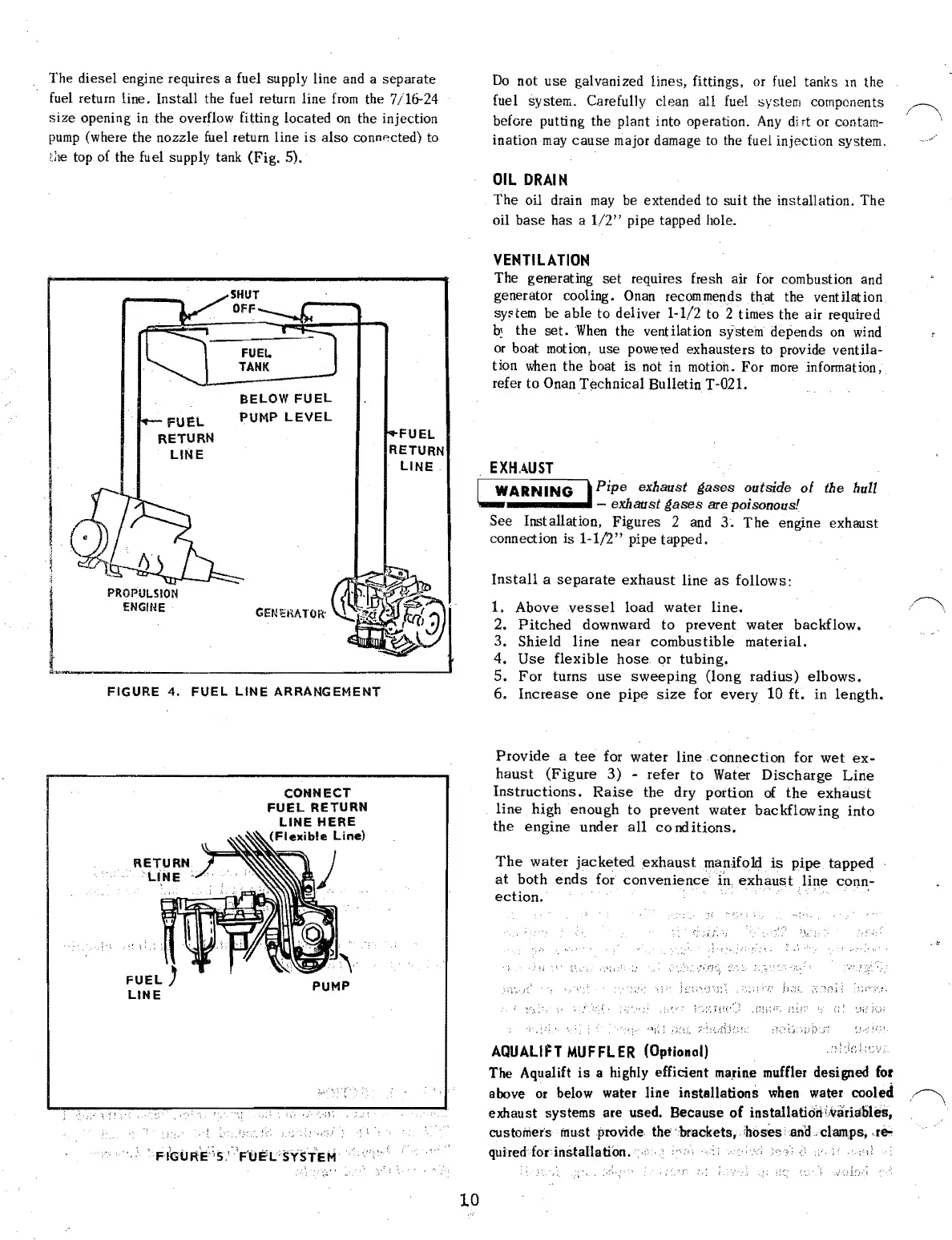
The diesel engine requires a fuel supply line and a separate
fuel
return line. Install the
fuel
return line
from
the 7/16-24
size
opening
in
the overflow fitting located
on
the injection
pump
(where the nozzle fuel return line
is
also connp.cted)
to
the
top of the fuel supply tank (Fig. 5).
Do
not
use
galvanized lines, fittings, or fuel tanks
10
the
fuel system. Carefully clean all fuel system components
before putting the plant into operation.
Any
di
rt or contam-
inationmay
cause
major damage
to
the fuel injection system.
OIL
DRAIN
The oil drain
may
be
extended to suit the installation. The
oil base has a
1/2"
pipe tapped hole.
VENTILATION
I
,
PROPUI.SION
ENGINE GENtiHATOR'
,~
BELOW
FUEL
PUMP
LEVEL
FUEL
RETURN
LINE
-J
FIGURE
4.
FUEL
LINE
ARRANGEMENT
The generating
set
requires fresh air
for
combustion and
generator cooling.
Onan
recom
mends
that
the vent
Hat
ion
sy~tem
be able to deliver 1-1/2 to 2 times the air required
b~
the
set.
When
the ventilation system depends
on
wind
or
boat
motion,
use powered exhausters
to
provide ventila-
tion
when
the boat
is
not in motioh. For
more
information,
refer to Onan Technical Bulletin T-021.
EXHAUST
, Pipe exbaust gases outside
of
tbe bull
L!ARNING
- exhaust
gases
are poisonous!
See Installation, Figures 2 and
3.
The
engine exhaust
connection
is
1-1/2"
pipe tapped.
Install
a
separate
exhaust
line
as
follows:
1. Above
vessel
load
water
line.
2.
Pitched
downward to prevent water
backflow.
3. Shield
line
near
combustible
material.
4.
Use
flexible
hose
or tubing.
5.
For
turns
use
sweeping
(long
radius)
elbows.
6.
Increase
one
pipe
size
for
every
10
ft. in
length.
Provide
a
tee
for
water
line
connection
for
wet
ex-
CONNECT
FUEL
RETURN
LINE
HERE
(Flexible
Line)
PUMP
:
t·
quired
forinstaUation.'·;
,0
10
haust
(Figure
3)
-
refer
to Water
Discharge
Line
Instructions.
Raise
the dry portion
of
the
exhaust
line
high enough
to
prevent water
backflowing
into
the
engine
under
all
co
nd
itions.
The
water
jacketed
exhaust
manifold
is
pipe
tapped
at
both
ends
for
convenience
in,
exhaust
line
conn,·
ection.
.'-:'.
'\:'
'}i;'
AQUALIFT
MUFFLER
(Optional)
'.
The Aqualift
is
a highly efficient
ma.rine
muffler designed
for
above
or
below water line installations
when
water cooled
exhaust systems are used. Because
of installatiorii,varil:t.iiles,
cus
tomer's
must .provide
the'
'brackets" ,hoses 'anlL
clam;ps,
,r&-
 Loading...

