OPERATION
CRANKCASE
OIL
Use an oil
with
the API designation CD/SE, or CD/SO
(formerly
OS)
that has passed the Series 3
Test
and at
least
Sequences
IIA
and·
ilIA
of the Automotive
Manu-
facturer's
MS
Sequence Te.sts.
(OM
oil which has passed
the Automotive Manufacturer's
MS
Sequence
Tests
and
the
MIL-L-2104B
Tests
may
also be used when ambient tempera-
tures are lower than
30°F.)
To reduce
oil
consumption
to
a
normal
level
in
the shortest time
on
a
new
or rebuilt
"]"
series
diesel engine,
use
CC
(formerly
OM)
oil
(pass-
ing
the
MS
Sequence
Tests)
for
the
first fill only
(50
to 100
hours), then change to the recommended oil.
TEMPERATURE
GRADE
Above
32°F
SAE
30
OaF
to
32°F
SAE
lOW-3~,
SW-20,
or
lOW,SW-30
SAE
SW-20
or
SW-30
Do
not
mix
brands
or
grades. Refer to Maintenance Section
for
recommended oil changes.
;0
RECOMMENDED
FUEL
Depends
on
operating condi tions. Use
NO.2
diesel fuel for
best
economy. Use
NO.
I diesel fuel (a)
when
ambient
tem-
perature
is
below
32
OF.,
or (b) at all temperatures during
long periods of light engine load,
(c)
if
preferred
by
user.
Use low sulfur content fuel having a pour point (ability to
filter) of at
least
100F. below the lowest expected tempera-
ture. Keep fuel clean
and
protected
from
adverse weather.
Leave some
room
for
expansion
when
filling the tank.
INITIAL
START
Check the engine
to
make sure
it
has been filled with oil
and that fuel system
is
air- free.
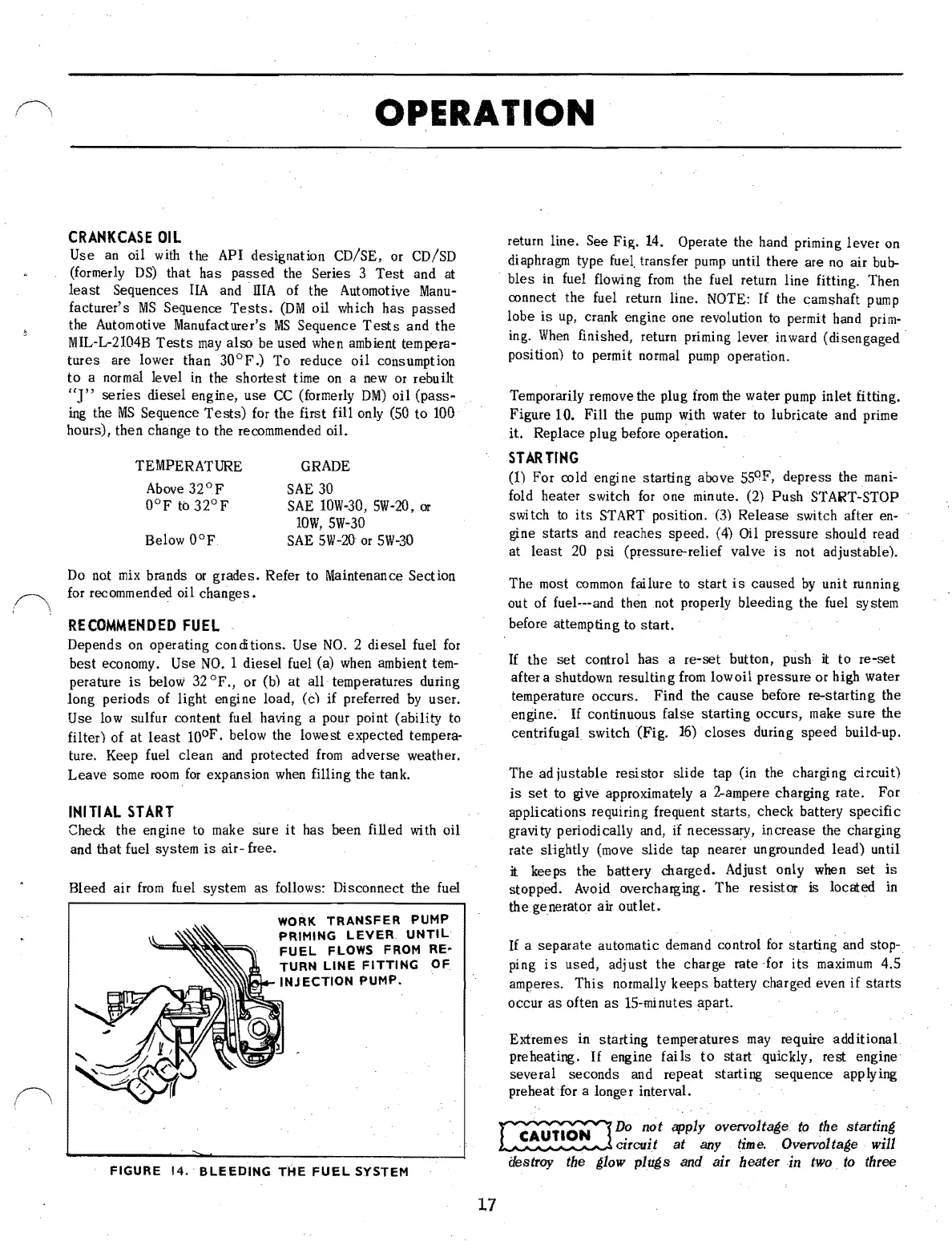
Bleed air
from
fuel system
as
follows: Disconnect the fuel
WORK
TRANSFER
PUMP
PRIMING
LEVER
UNTIL
FUEL
FLOWS FROM
RE·
TURN
LINE
FITTING
OF
INJECTION
PUMP.
FIGURE
14.·
BLEEDING
THE
FUEL
SYSTEM
return line. See Fig. 14. Operate the hand priming lever on
diaphragm type fuel. transfer
pump
until there are
no
air
bub-
bles
in
fuel flowing
from
the fuel return line fitting. Then
connect the fuel return line.
NOTE:
If
the camshaft
pump
lobe
is
up,
crank engine one revolution
to
permit hand
prim-
ing.
When
finished, return priming lever inward (disengaged·
position)
to
permit normal
pump
operation.
Temporarily remove the plug
from
the water
pump
inlet
fitting.
Figure 10. Fill the
pump
with water
to
lubricate and prime
it. Replace plug before
op~ration.
STARTING
(1) For cold engi ne starting above
55
0
F, depress the
mani-
fold heater switch
for
one minute. (2) Push START-STOP
switch
to
its
START
position.
(3)
Release switch after en-
gine starts and reaches speed. (4) Oil pressure should read
at
least
20 psi (pressure-relief valve
is
not adjustable).
The most
common
failure
to
start
is
caused
by
unit
r.unning
out of fuel---and then not properly bleeding the fuel system
before attempting
to
start.
If
the
set
control has a re-set button, push it to re-set
after a shutdown resulting
from
lowoil pressure or high water
temperature occurs. Find the
cause
before re-starting the
engine.
If
continuous false starting occurs, make sure the
centrifugal switch (Fig. 16)·
closes
during speed build-up.
The ad justable resistor slide tap (in the charging circuit)
is
set
to
give approximately a 2-ampere charging rate. For
applications requiring frequent starts, check battery specific
gravi
ty
periodically and, if necessary, increase the charging
rate slightly (move slide tap nearer ungrounded lead) until
it keeps the battery charged. Adjust only when
set
is
stopped.
Avoid
overcharging. The resistor is located in
the generator air outlet.
If
a separate automatic demand control
for
starting and stoP-.
ping
is
used, adjust the charge rate ·for
its
maximum
4.5
amperes. This normally keeps battery charged even
if
starts
occur
as
often
as
IS-minutes apart.
Extremes in starting temperatures
may
require additional
preheating.
If
engine
fails
to
start quickly, rest engine
several seconds and repeat starting sequence applying
preheat
for
a longer interval.
~
D?
n?t apply
oVen>:
..
olta;,e
to
the
starti~;,
~
cIrcuIt
at
any
time.
Overvolta;,e
WIll
destroy the ;,low plu;,s
and
air heater in two.
to
three
17
 Loading...

