/\
(f)
a..
0
I-
(j)
UJ
2
-
~
2:
UJ
12
A
1\
( >
If
I \
I
r
9
3
STARTING
MOTOR
SOLfNOID
ENERGIZES
4
~
~
<ii~
~
c}(f-
t
(J)
~
-IW
#~
ct:Ul
$&
(.!)o
~
0
::::l
-I
~
~~
~~
~
L1..
U
":l
<3'
ex
:x:
.>.
~4
I-
u
J'I
:z
~
SA...
-
lLI
~
(J
Ul
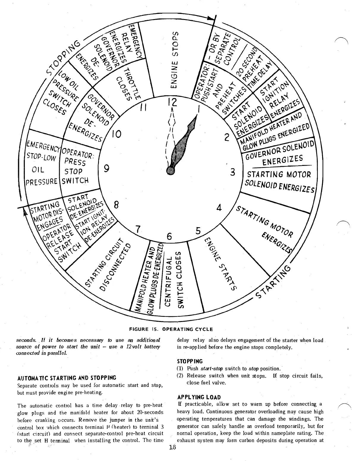
FIGURE
15.
OPERATING
CYCLE
seconds . . II
it
becomes necessary
to
use
an
additional
source
of
power
to
start the unit - use a
12
volt battery
connected
in
parallel.
AIJTOMA
TIC
STARTING
AIIID
STOPPING
Separate controls
may
be used for automatic
start
and stop,
but must provide engine pre-heating.
The automatic control
has
a time delay relay
to
pre-heat
glow
plugs
and the manifold heater
for
about
20-seconds
before cranking
occurs.
Remove the jumper
in
the
unit's
control box
'Nhich
connects
terminal H
(heater)
to
terminal 3
(start
circuit)
and connect separate-control
pre-heat
circuit
to
the
/:
.
set
H terminal
when
installing
the control. The time
,/"\
delay relay
also
delays
engagement
of
the
starter
when load
is
re-applied before the
engine
stops
completely. .
STOPPING
0)
Pllsh start-stop
switch
to stop position.
(2)
Release
switch when unit
stops.
If
stop
circuit
fails,
close
fuel valve.
APPLYING
LOAD
If
practicable,
allow
set
to
warm
up
before connecting a
heavy load. Continuous generator overloading may
cause
high
operating
temperatures
that
can damage the windings. The
generator can
safely
handle
an
overload temporarily, but for
normal operation, keep the load
wi
thin nameplate rating. The
exhaust
system
may
form
carbon
deposits
during operation
at
18
 Loading...

