GOV
ERNOR
ARM
----,---/
SENSITIVITY
ADJUSTING
RATCHET
\
GOVERNOR
STUD
SPEED
ADJUSTING
NUT
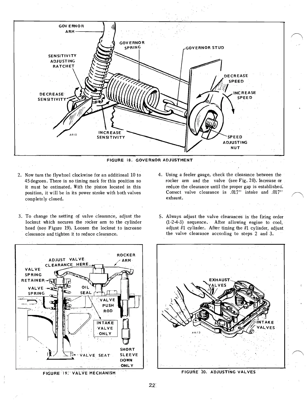
FIGURE
18.
GOVERNOR
ADJUSTMENT
2.
Now
turn the flywheel clockwise
for
an additional 10 to
4.
Using a feeler gauge, check the clearimce between the
45 degrees. There
is
no
timing
mark
for
this position so
rocker
arm
and the valve (see
Fig.
20). Increase
or
it must
be
estimated.
With
the piston located in this
reduce the clearance until the proper gap
is
established".
position, it will be in
its
power stroke with both valves
Correct valve clearance
is
.017" intake and .017"
completely closed.
exhaust.
3. To change the
setting
of valve Clearance, adjust
the
5.
Always adjust the valve clearances
in
the firing order
locknut which secures the rocker
arm
to the cylinder
(1-2-4-3) sequence. After allowing engine
to
cool,
head
(see
Figure 19). Loosen the locknut
to
increase adjust
#1
cylinder. After timing the
#1
cylinder, adjust
clearance and tighten it to reduce clearance.
the valve clearance according to
steps
2 and 3.
ROCKER
VALVE
SPRING
SEAT
SHORT
SLEEVE
DOWN
ONLY
FIGURE
20.
A'DJUSTING
VALVES
FIGURE
19.
VALvE
MECHAI\W;M
2Z
 Loading...

