;
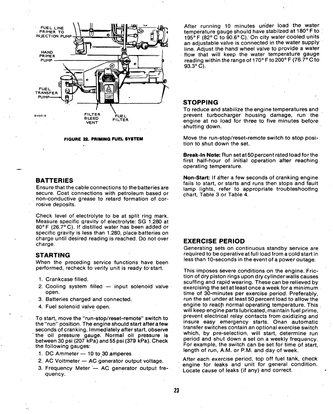
FUEL LINE
. PRIMER TO
INJECTION PUMP
HAND
PRIMER
PUMP
FUEL
TRANSFER
PUMP'
FILTER
BLEED
VENT
. FUEL
FILTER
FIGURE
22. PRIMING
FUEL
SYSTEM
After running 10 minutes under load the water
temperature gauge should have stabilzed at 180° F to
195° F (82° C to 90.6° C). On city water cooled units
an adjustable valve is connected in the water supply
line.
Adjust the hand wheel valve to provide a water
flow that will keep the water temperature gauge
reading within the range of 170°
F
to 200° F (76.7° C to
93.3° C).
STOPPING
To reduce and stabilize the engine temperatures and
prevent turbocharger housing damage, run the
engine at no load for three to five minutes before
shutting down.
Move the run-stop/reset-remote switch to stop
posi-
tion to shut down the set.
BATTERIES
Ensure that the cable connections to the batteries are
secure. Coat connections with petroleum based or
non-conductive grease to retard formation of cor-
rosive deposits.
Check level of electrolyte to be at split ring mark.
Measure specific gravity of electrolyte: SG 1.280 at
80° F (26.7° C). If distilled water has been added or
specific gravity is less than
1.280,
place batteries on
charge until desired reading is reached. Do not over
charge.
STARTING
When the preceding service functions have been
performed,
recheck to verify unit is ready to start.
1.
Crankcase filled.
2.
Cooling system filled — input solenoid valve
open.
3. Batteries charged and connected.
4.
Fuel solenoid valve open.
To start, move the "run-stop/reset-remote" switch to
the "run" position. The engine should start afterafew
seconds of cranking. Immediately after start, observe
the oil pressure gauge. Normal oil pressure is
between 30 psi (207 kPa) and 55 psi (379 kPa). Check
the following gauges:
1.
DC Ammeter — 10 to 30 .amperes
2.
AC Voltmeter — AC generator output voltage.
3. Frequency Meter — AC generator output fre-
quency.
Break-In Note: Run set at 50 percent rated load forthe
first half-hour of initial operation after reaching
operating temperature.
Non-Start: If after a few seconds of cranking engine
fails to start, or starts and runs then stops and fault
lamp lights, refer to appropriate troubleshooting
chart, Table 3 or Table 4.
EXERCISE
PERIOD
Generating sets on continuous standby service are
required to be operative at full load from a cold start in
less than 10-seconds in the event of a power outage.
This imposes severe conditions on the engine. Fric-
tion of drypiston rings upon dry cylinder walls causes
scuffing and rapid wearing. These can be relieved by
exercising the set at least once a week for a minimum
time of 30-minutes per exercise period. Preferably,
run the set under at least 50 percent load to allow the
engine to reacji normal operating temperature. This .
will keep engine parts lubricated, maintain fuel prime,
prevent electrical relay contacts from oxidizing and
insure easy emergency starts. Onan automatic
transfer switches contain an optional exercise switch
which,
by pre-selection, will start, determine run
period and shut down a set on a weekly frequency.
For example, the switch can be set for time of start,
length of run, A.M. or P.M. and day of week.
After each exercise period, top off fuel tank, check
engine for leaks and unit for general condition.
Locate cause of leaks (if any) and correct.
23
 Loading...