.
Reassembly and Installation:
When the carburetor
parts are clean and dry, reassemble using the following
procedure.
1.
If
removed during overhaul, slide in thethrottle shaft
and install the throttle plate using new screws, if
necessary. Before tightening the screws, the throttle
plate must be centered in the bore.
To
do
so,
remove
the throttle stop screw and completely close the
throttle lever. Seat the plate by gently pressing with
fingers into place, then tighten screws. Install the
choke shaft and plate in the same manor.
OCCUR
HERE
II
FS-1483.2
FIGURE
6-11.
MIXTURE NEEDLE INSPECTION
2.
Install idle mixture screw assembly. Turn in screw
until lightly seated and then out the number of turns
specified in Table
6-2.
Forcing the mixture adjustment
[BCAUTIONI
screws tight will damage the
needle and seat. Turn in only until light tension is
felt.
3.
Install needle valve and seat, fuel bowl gasket and
float
assembly. Make sure all clips and springs are
properly placed and the float moves freely without
binding (See Figure
6-1
2).
POSITION
HOOK
UNDER
TAB
ON
FLOAT
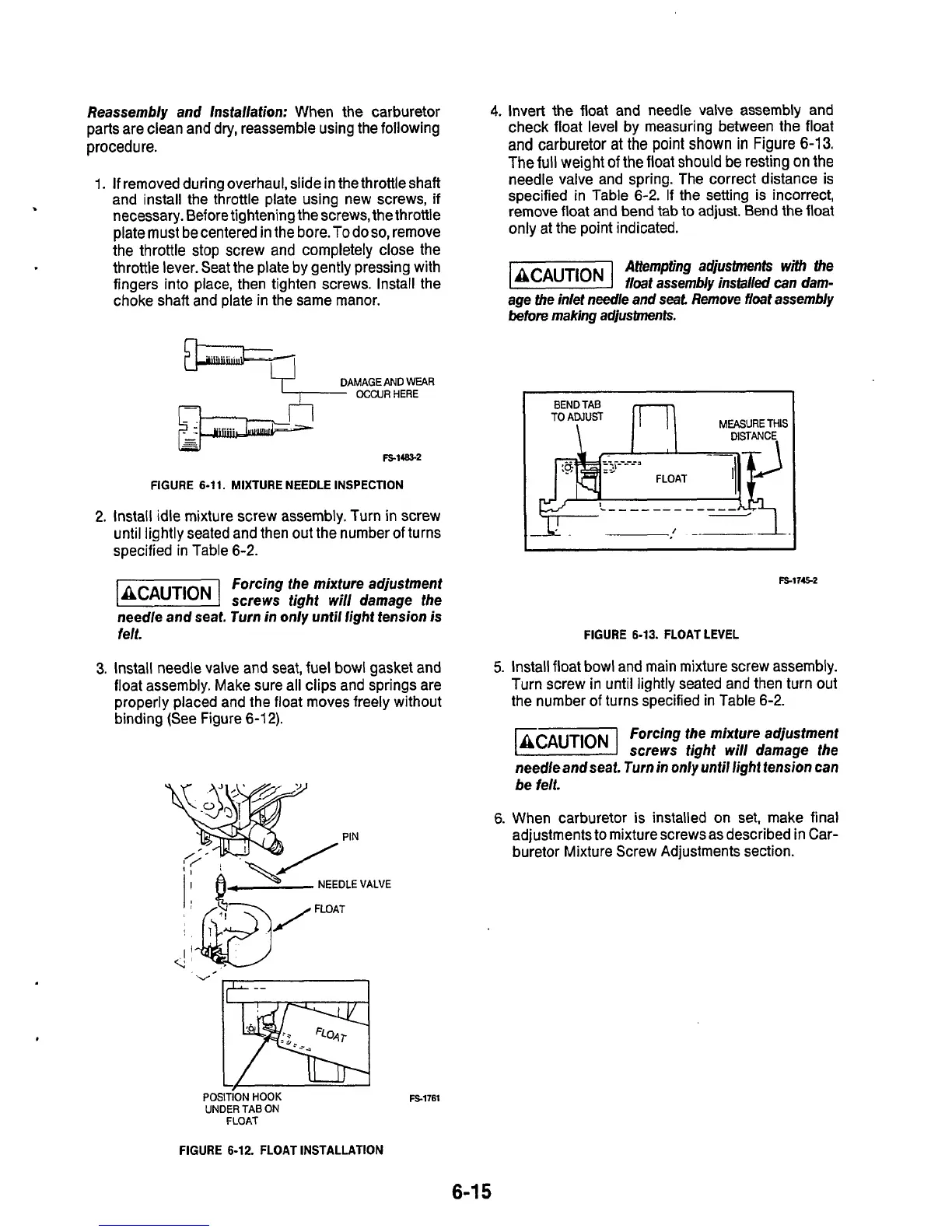
4.
Invert the float and needle valve assembly and
check float level by measuring between the float
and
carburetor
at
the
point
shown
in
Figure
6-13.
The
full
weight
of
the float should
be
resting on the
needle valve and spring. The correct distance is
specified in Table
6-2.
If the setting is incorrect,
remove float and bend tab to adjust. Bend the float
only at the point indicated.
Attempting
adjustments
with
dhe
laCAUTlONI
float assembly instal/@
can
dam-
age the inlet needle and
seat
Remove float assembly
before
making
adjustments.
FS-17E-2
FIGURE 6-13. FLOAT LEVEL
5.
Install float bowl and main mixture screw assembly.
Turn screw in until lightly seated and then turn out
the number
of
turns specified in Table
6-2.
Forcing the mixture adjustment
screws tight will damage the
needle and seat.
Turn
in
only until light tension can
be felt.
6.
When carburetor
is
installed on set, make final
adjustments
to
mixture screws as described in Car-
buretor Mixture Screw Adjustments section.
FS-1761
FIGURE
6-12.
FLOAT INSTALLATION
6-1
5

 Loading...
