Installing Piston
in
Cylinder:
When installing the pis-
ton assembly, observe markings on the connecting rod,
cap,
and
splasher
and
assemble
in
correct position.
See
Figure
9-22.
3.
Tap piston down into bore with handle end of
hammer until connecting rod is seated on crankpin.
Check
crankpin
clearance
before
proceeding
to
#4
step (see Crankpin Clearance section).
1.
2.
+
Turn Crankshaft
to
position crankpin at bottom
of
its
stroke.
Lubricate piston assembly and inside
of
cylinder.
Compress rings with
a
ring compressor
as
shown
in
Figure
9-23.
4.
Lubricate the rod crankpin and install the connect-
ing rod cap. Tighten connecting rod bolts to speci-
fied torque.
The bearing cap must be tapped several times
to
properly align it with the connecting rod. Clearance
varies on the crankpin
if
this
is
not done. Crank the
engine by hand
to
see that the crankshaft turns
freely without binding.
Crankpin Clearance
1.
Mark parts
so
they can be installed in their original
positions, and wipe all parts clean of any oil or
grease.
2.
Place a piece of the correct size Plasti-gageacross
the full width
of
the rod cap about
1
/4
inch
(6
rnrn)
off
center.
3.
Install the rod cap and tighten to the specified
torque.
Do
not rotate the crankshaft after the cap is
in place.
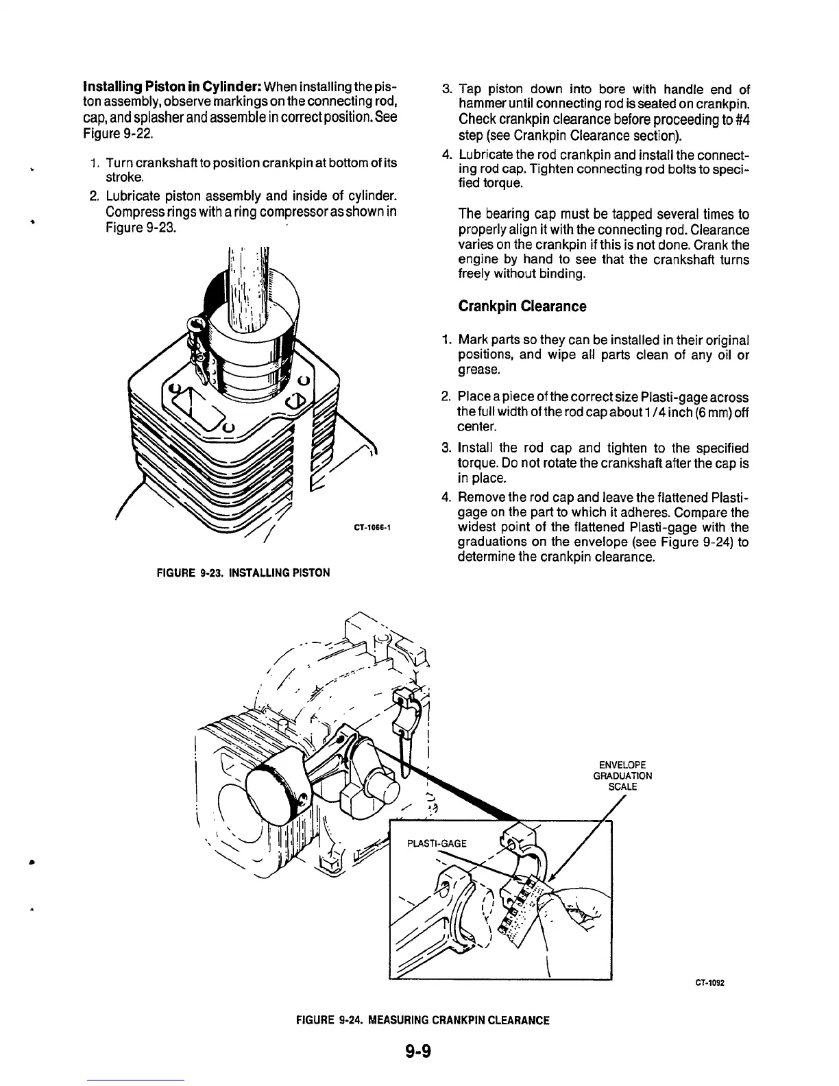
4.
Remove the rod cap and leave the flattened Plasti-
gage on the part to which it adheres. Compare the
widest point of the flattened Plasti-gage with the
graduations on the envelope (see Figure
9-24)
to
determine the crankpin clearance.
FIGURE
9-23.
INSTALLING PISTON
FIGURE
9-24.
MEASURING CRANKPIN CLEARANCE
9-9
CT-1092

 Loading...
