Use a new piston pin to check connecting rod for wear.
A
push fit clearance is required and varies from engine
to engine.
If
a new piston pin falls through a dry rod pin
bore as a result of its own weight, replace the rod or
bushing as required.
Piston
Pin
Inspection:
Replace piston pin that is
cracked, scored, or out of round more than 0.002 inch
(0.05
mm).
Piston Clearance
Proper piston tolerances must be maintained for satis-
factory operation. Use a micrometer to measure the
piston diameter at the pointshown in Figure9-20. When
the cylinder bore is measured (see Cylinder
Blocksec-
lion),
subtract the piston diameter from the cylinder bore
diameter to obtain the piston pin
to
cylinder wall clear-
ance. Refer to the Dimensions and Clearances section
for the recommended piston clearance.
CT-1063
FIGURE
9-20.
PISTON
CLEARANCE
MEASUREMENT
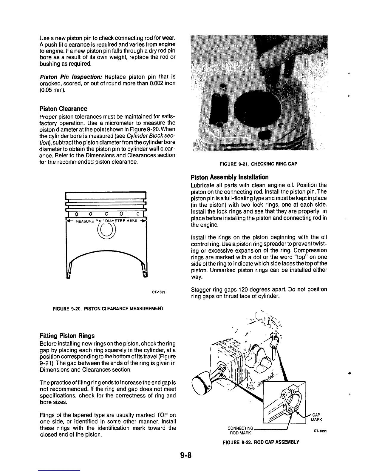
Fitting Piston Rings
Before installing new rings on the piston, check the ring
gap by placing each ring squarely in the cylinder, at a
position corresponding to the bottom of its travel (Figure
9-21). The gap between the ends of the ring is given in
Dimensions and Clearances section.
The practice of filing ring ends to increase the end gap is
not recommended.
If
the ring end gap does not meet
specifications, check for the correctness of ring and
bore sizes.
Rings of the tapered type are usually marked
TOP
on
one side, or identified in some other manner. Install
these rings with the identification mark toward the
closed end
of
the piston.
FIGURE
9-21.
CHECKING RING
GAP
Piston Assembly Installation
Lubricate all parts with clean engine oil. Position the
piston on the connecting rod. Install the piston pin. The
piston pin isafull-floating type and must be kept in place
(in the piston) with two lock rings, one at each side.
Install the lock rings and see that they are properly
in
place before installing the piston and connecting rod in
the engine.
Install the rings on the piston beginning with the
oil
control ring. Use a piston ring spreader to prevent twist-
ing or excessive expansion
of
the ring. Compression
rings are marked with a dot or the word "top" on one
side
of
the ring to indicate which side faces the top
of
the
piston. Unmarked piston rings can be installed either
way.
Stagger ring gaps 120 degrees apart. Do not position
ring gaps on thrust face of cylinder.
CONNECTING
-/
ROD
MARK
CT-1091
FIGURE
9-22.
ROD
CAP
ASSEMBLY
9-8

 Loading...
