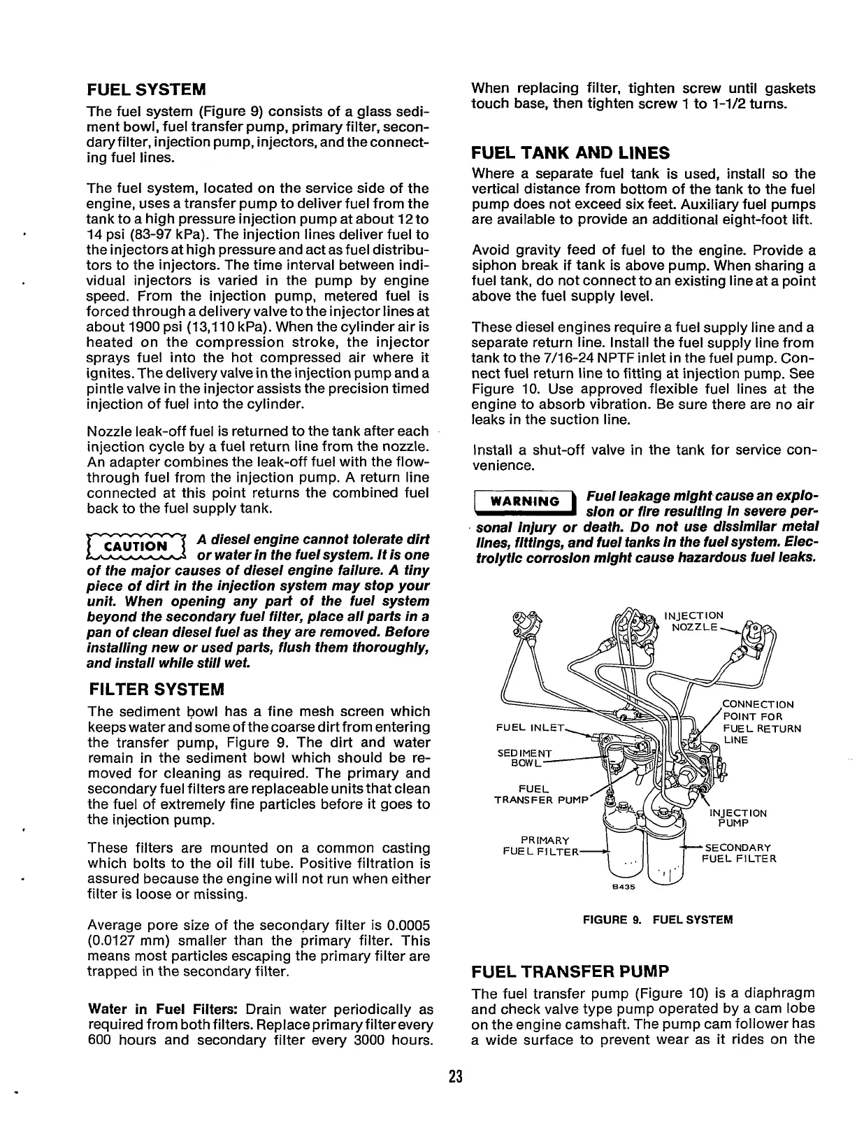
FUEL SYSTEM
The fuel system (Figure
9)
consists of a glass sedi-
ment bowl, fuel transfer pump, primary filter, secon-
daryfilter, injection pump, injectors, and the connect-
ing fuel lines.
The fuel system, located on the service side of the
engine, uses a transfer pump to deliver fuel from the
tank to a
high
pressure injection pump at about
12
to
14
psi
(83-97
kPa). The injection lines deliver fuel to
the injectors at high pressure and act as fuel distribu-
tors to the injectors. The time interval between indi-
vidual injectors is varied
in
the pump by engine
speed. From the injection pump, metered fuel is
forced through a delivery valve to the injector lines at
about
1900
psi
(13,110
kPa). When the cylinder air is
heated on the compression stroke, the injector
sprays fuel into the hot compressed air where it
ignites. The delivery valve
in
the injection pump and a
pintle valve in the injector assists the precision timed
injection of fuel into the cylinder.
Nozzle leak-off fuel is returned to the tank after each
injection cycle by a fuel return line from the nozzle.
An adapter combines the leak-off fuel with the flow-
through fuel from the injection pump. A return line
connected at this point returns the combined fuel
back to the fuel supply tank.
A
diesel engine cannot tolerate dirt
or water in the fuel system. It is one
of the major causes of diesel engine failure.
A
tiny
piece of dirt in the injection system may stop your
unit. When opening any part of the fuel system
beyond the secondary fuel filter, place all parts in a
pan of clean diesel fuel as they are removed. Before
installing new or used parts, flush them thoroughly,
and install while still wet.
FILTER SYSTEM
The sediment bowl has a fine mesh screen which
keeps water and some of the coarse dirt from entering
the transfer pump, Figure
9.
The dirt and water
remain in the sediment bowl which should be re-
moved for cleaning as required. The primary and
secondary fuel filters are replaceable units that clean
the fuel of extremely fine particles before it goes to
the injection pump.
These filters are mounted on a common casting
which bolts to the oil fill tube. Positive filtration is
assured because the engine will not run when either
filter is loose or missing.
Average pore size of the secondary filter is
0.0005
(0.0127
mm) smaller than the primary filter. This
means most particles escaping the primary filter are
trapped
in
the secondary filter.
Water in Fuel Filters:
Drain water periodically as
required from both filters. Replace primary filter every
600
hours and secondary filter every
3000
hours.
When replacing filter, tighten screw until gaskets
touch base, then tighten screw
1
to
1-1/2
turns.
FUEL TANK AND LINES
Where a separate fuel tank is used, install
so
the
vertical distance from bottom of the tank to the fuel
pump does not exceed six feet. Auxiliary fuel pumps
are available to provide an additional eight-foot lift.
Avoid gravity feed of fuel to the engine. Provide a
siphon break if tank is above pump. When sharing a
fuel tank, do not connect to an existing line at a point
above the fuel supply level.
These diesel engines require a fuel supply line and a
separate return line. Install the fuel supply line from
tank to the
7/16-24
NPTF inlet in the fuel pump. Con-
nect fuel return line to fitting at injection pump. See
Figure
IO.
Use approved flexible fuel lines at the
engine to absorb vibration. Be sure there are no air
leaks
in
the suction line.
Install a shut-off valve
in
the tank for service con-
venience.
WARNING
Fuel leakage mlght cause an explo-
m
sion
or
fire resulting In severe per-
.
sonal injury or death.
Do
not use dissimilar metal
Ilnes, fittings, and fuel tanks In the fuel system. Elec-
trolytic corrosion mlght cause hazardous fuel leaks.
FUEL
FILTER
WU
8435
FIGURE
9.
FUEL
SYSTEM
FUEL TRANSFER PUMP
The fuel transfer pump (Figure
10)
is a diaphragm
and check valve type pump operated by a cam lobe
on the engine camshaft. The pump cam follower has
a wide surface to prevent wear as
it
rides on the
23
Redistribution or publication of this document,
by any means, is strictly prohibited.