Assembly:
camshaft lobe. The priming lever is manually oper-
ated to prime and bleed the system.
The diaphrgam spring maintains required fuel
pressure to the injection pump. Fuel pressure should
be 12-14 psi (83-97 kPa) when operating at 1800 rpm.
Fuel pump pressure may be checked'by connecting a
pressure gauge and tee at the fuel outlet. A vacuum
gauge connected at the fuel inlet will show whether
the pump has enough capacity to lift fuel about
6
feet
(1.83 m). The fuel pump should produce
15
to 18
inches (381 to 457 mm) of vacuum at sea level.
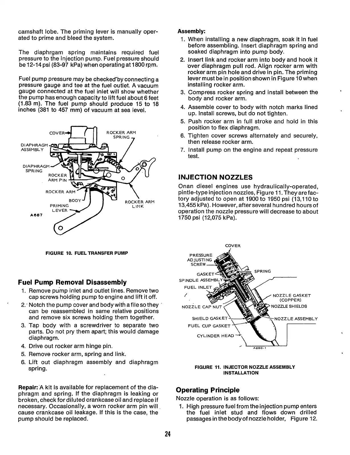
ROCKER ARM
SPRING
.,
COVER
DlAPHRAGl
SPRINT.
PRIMING LiFlK
FIGURE
10.
FUEL TRANSFER PUMP
Fuel Pump Removal Disassembly
1.
Remove pump inlet and outlet lines. Remove two
cap screws holding pump to engine and lift it off.
2: Notch the pump cover and body with afileso they
'
3.
4.
5.
6.
can be reassembled in same-relative positions
and remove six screws holding them together.
Tap body with a screwdriver to separate two
parts. Do not pry them apart; this would damage
d ia p
h
rag m.
Drive out rocker arm hinge pin.
Remove rocker arm, spring and link.
Lift out diaphragm assembly and diaphragm
spring.
Repair:'A kit is available for replacement of the dia-
phragm and spring. If the diaphragm is leaking or
broken, check for diluted crankcase oil and replace if
necessary. Occasionally, a worn rocker arm pin will
cause crankcase oil leakage.
If
this is the case, the
pump should be replaced.
1.
2.
3.
4.
5.
6.
7.
When installing a new diaphragm, soak it in fuel
before assembling. Insert diaphragm spring and
soaked diaphragm into pump body.
Insert link and rocker arm into body and hook it
'over diaphragm pull rod. Align rocker arm with
rocker arm pin hole and drive
in
pin. The priming
lever must be
in
position shown in Figure
10
when
installing rocker arm.
Compress rocker spring and install between the
body and rocker arm.
Assemble cover to body with notch marks lined
up. Install screws, but do not tighten.
Push rocker arm
in
full stroke and hold in this
position to flex diaphragm.
Tighten cover screws alternately and securely,
then release rocker arm.
Install pump on the engine and repeat pressure
test.
INJECTION NOZZLES
Onan diesel engines use hydraulically-operated,
pintle-type injection nozzles, Figure
11.
They arefac-
tory adjusted to open at 1900 to 1950 psi
(13,110
to
13,455 kPa). However, after several hundred hours of
operation the nozzle pressure will decrease to about
1750
psi
(1
2,075
k Pa).
COVER
SPINDLE ASSEM
NOZZLE GASKET
NOZZLE CA
OZZLE
SHIELDS
OZZLE ASSEMBLY SHIELD CASK
FUEL CUP GASKET
CYLINDER HEAD
,-
A880-1
FIGURE
11.
INJECTOR NOZZLE ASSEMBLY
INSTALLATION
Operating Principle
Nozzle operation is as follows:
1.
High pressure fuel from the injection pump enters
the fuel inlet stud and flows down drilled
passages
in
the body
of
nozzle holder, Figure 12.
24
Redistribution or publication of this document,
by any means, is strictly prohibited.