NOZZLE INSTALLATION
Before installing the injection nozzles in the engine,
thoroughly clean each mounting recess.
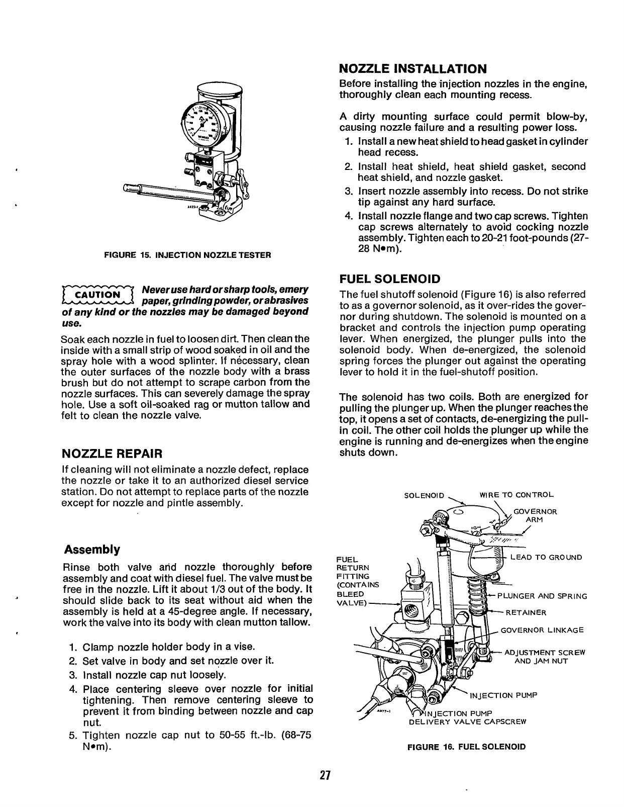
FIGURE
15.
INJECTION NOZZLE TESTER
Never use hard or sharp tools, emery
paper, grinding powder, or abrasives
of
any kind or the nozzles may be damaged beyond
use.
Soak each nozzle in fuel to loosen dirt. Then clean the
inside with a small strip of wood soaked in oil and the
spray hole with a wood splinter. If necessary, clean
the outer surfaces of the nozzle body with a brass
brush but do not attempt to scrape carbon from the
nozzle surfaces. This can severely damage the spray
hole. Use a soft oil-soaked rag or mutton tallow and
felt to clean the nozzle valve.
NOZZLE REPAIR
If cleaning will not eliminate a nozzle defect, replace
the nozzle or take it to an authorized diesel service
station.
Do
not attempt to replace parts of the nozzle
except for nozzle and pintle assembly.
Assembly
Rinse both valve and nozzle thoroughly before
assembly and coat with diesel fuel. The valve must be
free in the nozzle. Lift
it
about
1/3
out of the body.
It
should slide back to its seat without aid when the
assembly is held at a 45-degree angle.
If
necessary,
work the valve into its body with clean mutton tallow.
1.
2.
3.
4.
5.
Clamp nozzle holder body in a vise.
Set valve in body and set nozzle over
it.
Install nozzle cap nut loosely.
Place centering sleeve over nozzle for initial
tightening. Then remove centering sleeve to
prevent
it
from binding between nozzle and cap
nut.
Tighten nozzle cap nut to
50-55
ft.-lb. (68-75
Nom).
A
dirty mounting surface could permit blow-by,
causing nozzle failure and a resulting power
loss.
1.
Install a new heat shield to head gasket in cylinder
head recess.
2. Install heat shield, heat shield gasket, second
heat shield, and nozzle gasket.
3.
Insert nozzle assembly into recess.
Do
not strike
tip against any hard surface.
4.
Install nozzle flange and two cap screws. Tighten
cap screws alternately to avoid cocking nozzle
assembly. Tighten each to 20-21 foot-pounds (27-
28
Nom).
FUEL SOLENOID
The fuel shutoff solenoid (Figure 16) is also referred
to as a governor solenoid, as
it
over-rides the gover-
nor during shutdown. The solenoid
is
mounted on a
bracket and controls the injection pump operating
lever. When energized, the plunger pulls into the
solenoid body. When de-energized, the solenoid
spring forces the plunger out against the operating
lever to hold
it
in the fuel-shutoff position.
The solenoid has two coils. Both are energized for
pulling the plunger up. When the plunger reaches the
top,
it
opens a set of contacts, de-energizing the pull-
in coil. The other coil holds the plunger up while the
engine is running and de-energizes when the engine
shuts down.
SOLENOID
-
WIRE TO CONTROL
FUEL
D
TO GROUND
RETURN
FITTING
NGER AND SPRING
GOVERNOR LINKAGE
ADJUSTMENT SCREW
AND JAM NUT
INJECTION PUMP
N IECTION PUMP
DELIVERY
VALVE
CAPSCREW
0
FIGURE
16.
FUEL SOLENOID
21
Redistribution or publication of this document,
by any means, is strictly prohibited.