When the tappet slips off each lobe of the camshaft,
the spring loaded plunger is forced down opening the
fuel supply port to the fuel sump. This allows fuel
under low pressure from the transfer pump and fuel
sump to fill the cavity between the top end of the
plunger and the delivery valve. The plunger is then
ready for the up stroke.
-
.lo1
.098
.095
,092
-089
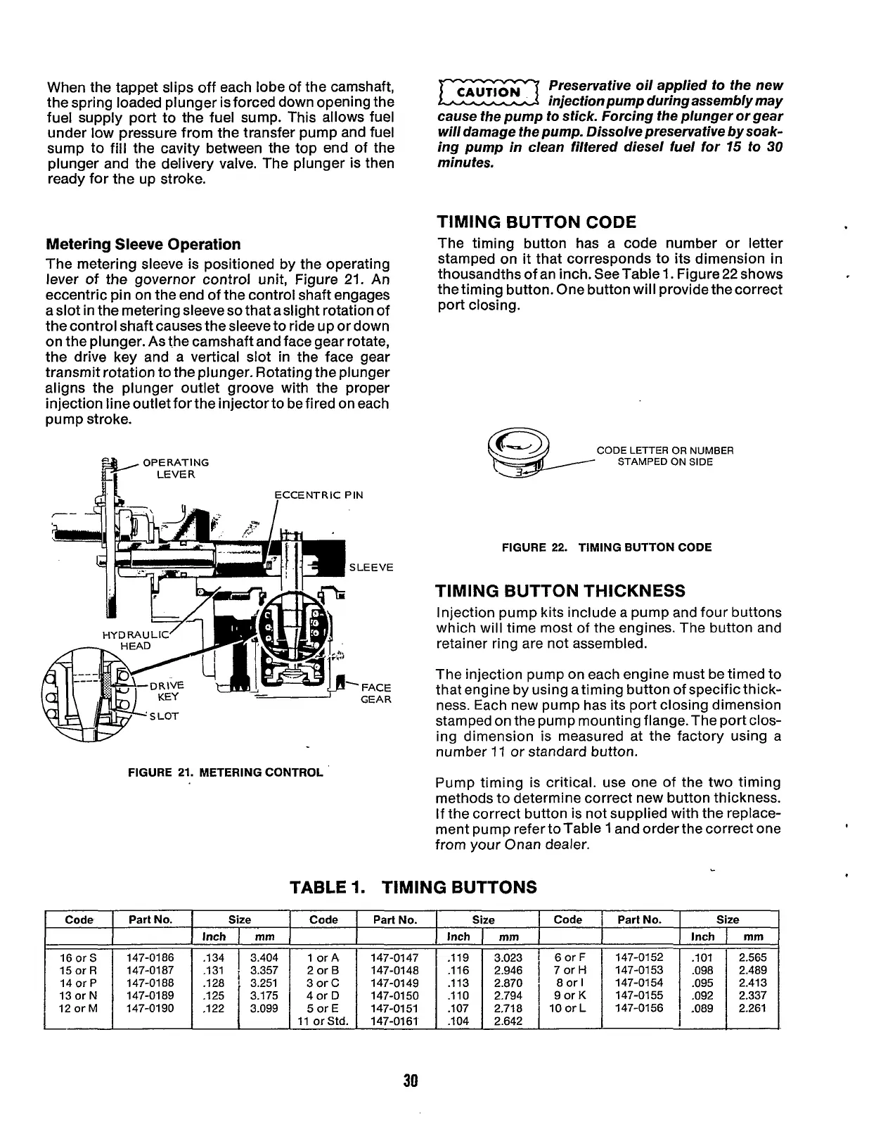
Metering Sleeve Operation
The metering sleeve is positioned by the operating
lever
of
the governor control
unit,
Figure
21.
An
eccentric pin on the end of the control shaft engages
a slot in the metering sleeveso that aslight rotation of
the control shaft causes the sleeve to ride up or down
on the plunger. As the camshaft and face gear rotate,
the drive key and a vertical slot in the face gear
transmit rotation to the plunger. Rotating the plunger
aligns the plunger outlet groove with the proper
injection line outlet for the injector to be fired on each
pump stroke.
2.565
2.489
2.413
2.337
2.261
ECCENTRIC PIN
F
SLEEVE
-
FACE
GEAR
Code
16
or
S
15
or
R
14
or
P
13
or
N
12
or
M
FIGURE
21.
METERING CONTROL
Part
NO.
I
C
I
Inch
147-01
88
147-01 89 .125
147-01 90
Preservative oil applied to the new
injection pump during assembly may
cause the pump to stick. Forcing the plunger or gear
will damage the pump. Dissolve preservative by soak-
ing pump in clean filtered diesel fuel for
75
to
30
minutes.
TIMING BUTTON CODE
The timing button has a code number or letter
stamped on
it
that corresponds to its dimension
in
thousandths of an inch. See Table
I.
Figure
22
shows
the timing button. One button will provide the correct
port closing.
CODE LETTER
OR
NUMBER
STAMPED ON SIDE
FIGURE
22.
TIMING BUTTON CODE
TIMING BUTTON THICKNESS
Injection pump kits include a pump and four buttons
which will time most of the engines. The button and
retainer ring are not assembled.
The injection pump on each engine must be timed to
that engine by using a timing button of specific thick-
ness. Each new pump has its port closing dimension
stamped on the pump mounting flange. The port clos-
ing dimension is measured at the factory using a
number
17
or standard button.
Pump timing is critical. use one of the two timing
methods to determine correct new button thickness.
If the correct button
is
not supplied with the replace-
ment pump refer to Table
1
and order the correct one
from your Onan dealer.
I
L
TABLE
1.
TIMING
BUTTONS
e
I
Code
I
Part No.
rnrn
I
147-01 51
Size
Inch
I
rnm
2.794
2.71
8
2.642
Code
~
6orF
7
or
H
8
or
I
9orK
10
or
L
Part
No.
147-01 52
147-01 53
147-01 54
147-01
55
147-01 56
I
30
Redistribution or publication of this document,
by any means, is strictly prohibited.