INJECTION
PUMP
INSTALLATION
Be sure the steel shims between the pump and the
cylinder block mounting are the same. These shims
maintain proper gear backlash. The number stamped
on the cylinder block injection pump mounting pad
indicates the proper shim thickness. This thickness
does not change when a new pump is installed. It only
changes when a new cylinder block is installed.
1.
Turn engine in direction of rotation (clockwise
when viewed from the front of engine) until
number one cylinder is on a compression stroke
and the
PC
mark on flywheel lines up with timing
pointer on gearcase (Figure 27). Rotation clock-
wise also takes out all gear backlash in that
direction.
Look into injection pump mounting hole to verify
that one intake lobe points outward and down
45
degrees.
2.
Remove screw (Figure
30)
on side of injection
pump. Rotate drive gear until a 0.125 inch (3.175
mrn) brass rod can be inserted into drive gearslot.
This locks the gear in position, when installing
injection pump on engine.
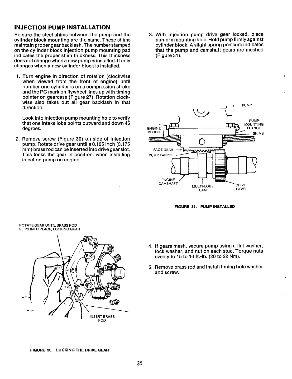
3. With injection pump drive gear locked, place
pump in mounting hole. Hold pump firmly against
cylinder block.
A
slight spring pressure indicates
that the pump and camshaft gears are meshed
(Figure 31).
PUMP
MOUNTING
m
1
ENGINE
/
Lf'
..I I,
7,
I
nnr
CAMSHAFT
IVlUL
I
I-LUPC
CAM GEAR
FIGURE
31.
PUMP
INSTALLED
ROTATE GEAR UNTIL BRASS
ROD
SLIPS INTO PLACE, LOCKING GEAR
ROD
FIGURE
30.
LOCKING THE DRIVE GEAR
4.
If gears mesh, secure pump using a flat washer,
lock washer, and nut on each stud. Torque nuts
evenly to
15
to 16 ft.-lb.
(20
to 22 Nm).
5.
Remove brass rod and install timing hole washer
and screw.
34
Redistribution or publication of this document,
by any means, is strictly prohibited.