BYPASSVALVE
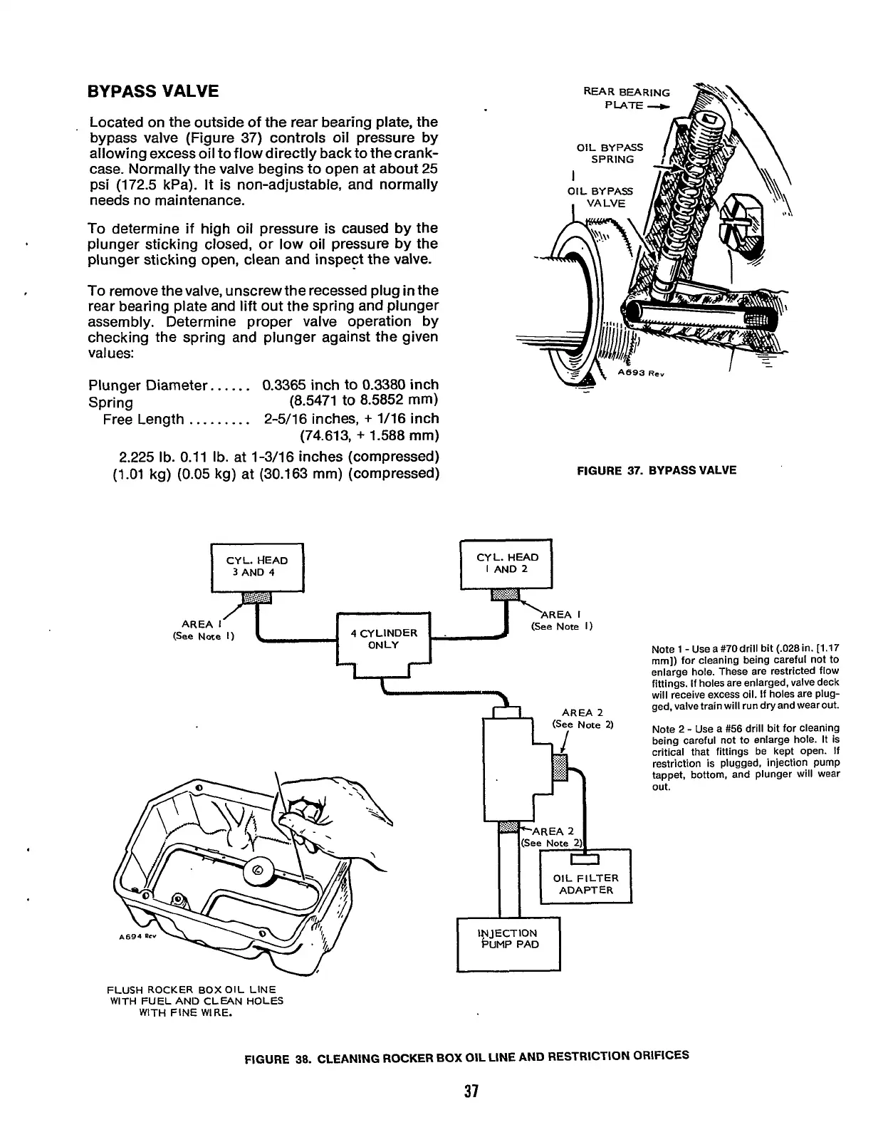
Located on the outside of the rear bearing plate, the
bypass valve (Figure
37)
controls oil pressure
by
allowing excess oil to flow directly back to the crank-
case. Normally the valve begins to open at about 25
psi (172.5 kPa).
It
is
non-adjustable, and normally
needs no maintenance.
To
determine
if
high oil pressure is caused
by
the
plunger sticking closed,
or
low oil pressure
by
the
plunger sticking open, clean and inspect the valve.
To
remove the valve, unscrew the recessed plug
in
the
rear bearing plate and lift out the spring and plunger
assembly. Determine proper valve operation by
checking the spring and plunger against the given
values:
Plunger Diameter..
....
0.3365 inch to 0.3380 inch
Spring (8.5471 to 8.5852
mm)
Free Length
.........
2-5/16 inches,
+
1/16 inch
(74.613,
+
1.588
mm)
2.225 Ib. 0.11
Ib.
at 1-3/16 inches (compressed)
(1.01 kg)
(0.05
kg) at (30.163 mm) (compressed)
CYL. HEAD
3
AND
4
REAR
BEARING
OIL BYPASS
OIL BYPASS
-
FIGURE
37.
BYPASS
VALVE
CYL. HEAD
I
AND
2
AREA
I
(See Note
I)
(See Note
1)
4
CYLINDER
FLUSH ROCKER BOX OIL LINE
WITH FUEL AND CLEAN HOLES
WITH FINE WIRE.
INJECTION
PUMP PAD
Note1 -Usea#70drill bit (.028in. [1.17
mrn]) for cleaning being careful not to
enlarge hole. These are restricted flow
fittings.
If
holes are enlarged, valve deck
will receive excess oil. If holes are plug-
ged, valve train will run dry and wear out.
Note 2
-
Use a
#56
drill bit for cleaning
being careful not to enlarge hole. It is
critical that fittings be kept open.
If
restriction is plugged, injection pump
tappet, bottom, and plunger will wear
out.
FIGURE
38.
CLEANING ROCKER
BOX
OIL LINE AND RESTRICTION ORIFICES
37
Redistribution or publication of this document,
by any means, is strictly prohibited.