1500 North Belcher Road, Clearwater, FL 33765 • Tel (727) 447-6140 • Fax (727) 442-5699 • sales@onicon.com
Turbine Flow Meter Manual 05/13 - 0721-1 / 13518 Page 10
FLOW DIRECTION
STRAIGHT RUN REQUIREMENTS FOR INSERTION TURBINE FLOW METERS
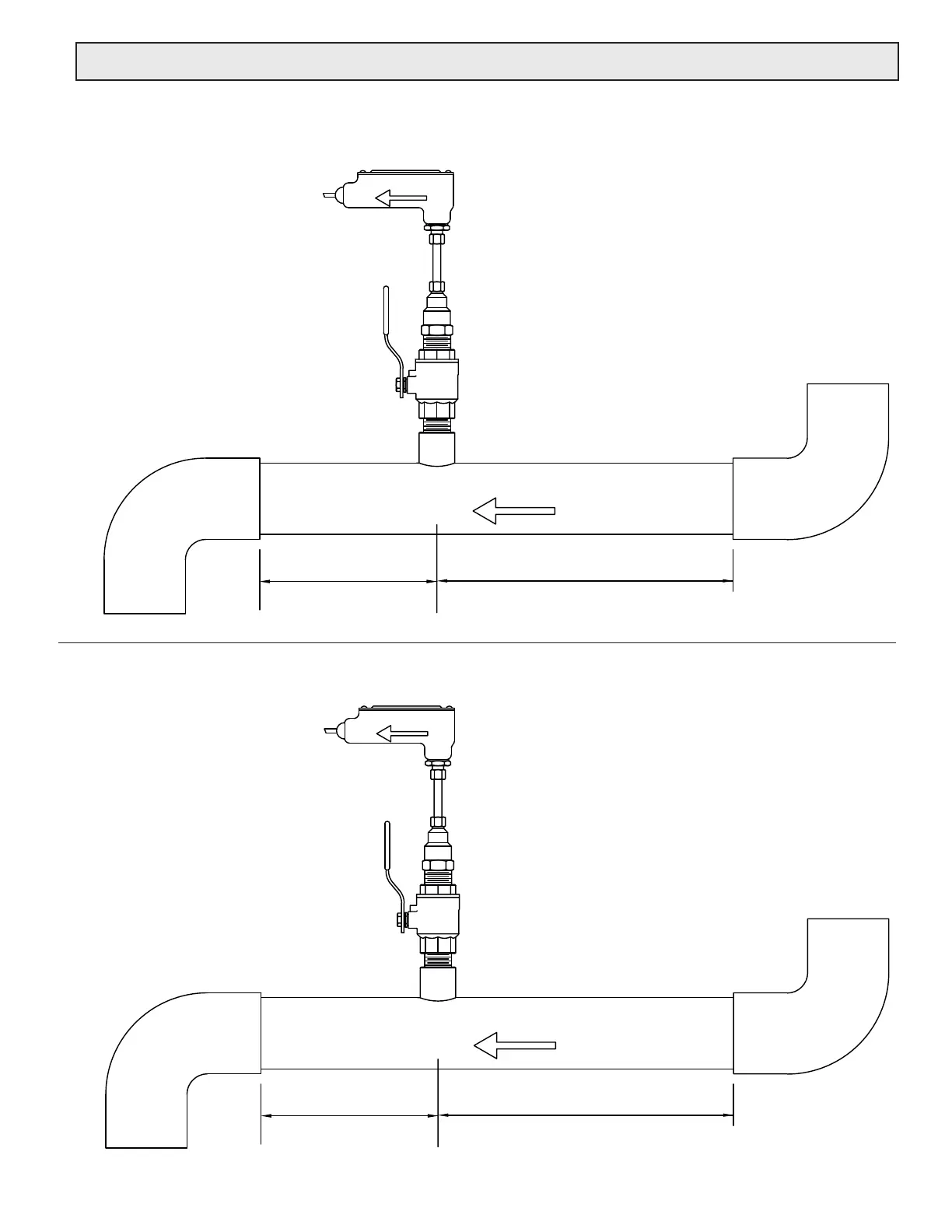
Series F-1100 Single Turbine Flow Meters
GENERAL PRACTICES
1. For best results, install the ow meter in a straight run of pipe,
free of bends, tees, valves, transitions, and obstructions for a
distance of at least 20 pipe diameters upstream and 5 diameters
downstream.
2. Longer straight runs may be required in applications where the
meter is placed downstream from devices which cause unusual
ow prole disruption or swirl, for example, modulating valves or
two elbows in close proximity and out of plane, etc.
3. If there is not sufcient straight run, allow 80% of the run upstream and
20% of the run downstream. If the total length of straight run is less
than 20 diameters, performance may seriously
degrade, and consideration should be given to
changing to the series F-1200 Dual Turbine
Flow Meter.
FLOW DIRECTION
Minimum upstream
straight run distance
20 pipe diameters from any
valve, elbow, tting, etc.
Minimum downstream
straight run distance
5 pipe diameters to any
valve, elbow, tting, etc.
Series F-1200 Dual Turbine Flow Meters
GENERAL PRACTICES
1. For best results, install the ow meter in a straight run of pipe,
free of bends, tees, valves, transitions, and obstructions for a
distance of 10 pipe diameters upstream and 5 diameters
downstream.
2. Longer straight runs may be required in applications where the
meter is placed downstream from devices which cause unusual
ow prole disruption or swirl, for example, modulating valves or
two elbows in close proximity and out of plane, etc.
3. If there is not sufcient straight run, allow 80% of the run upstream and
20% of the run downstream. If the total length of straight run is less
than 70% of recommended distance, performance
may degrade and consideration should be given to
changing to the F-3000 Series Inline
Electromagnetic ow meter.
FLOW DIRECTION
Minimum upstream
straight run distance
10 pipe diameters from any
valve, elbow, tting, etc.
Minimum downstream
straight run distance
5 pipe diameters to any
valve, elbow, tting, etc.
3.2 INSERTION METER STRAIGHT RUN REQUIREMENTS
 Loading...


