1500 North Belcher Road, Clearwater, FL 33765 • Tel (727) 447-6140 • Fax (727) 442-5699 • sales@onicon.com
Turbine Flow Meter Manual 05/13 - 0721-1 / 13518 Page 23
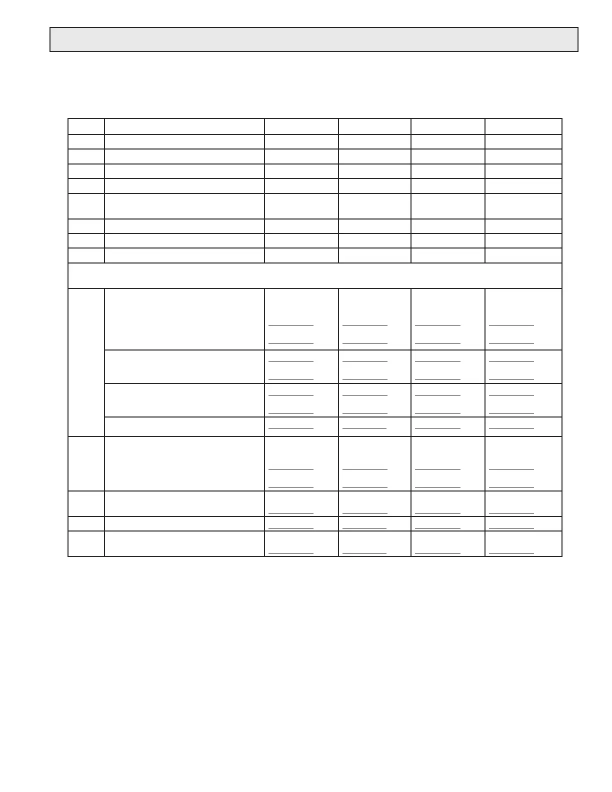
4.3 INSERTION METER START-UP AND COMMISSIONING WORKSHEET
Please read all installation instructions carefully prior to proceeding with these steps. Wiring
diagrams are located in the appendix. Use the following worksheet for checking off the
commissioning steps and recording measured values:
STEP TEST / MEASUREMENT S/N: _______ S/N: _______ S/N: _______ S/N: ______
1 Meter location
2 Conrm pipe size
3 Insertion depth and orientation
4 Control system programming
5 Match display or BTU meter serial#
(if ordered)
6 Signal connections veried
7 Supply voltage veried
8 Connect power
The following steps require ow in the pipe. Flow signal readings should be taken while holding the ow rate con-
stant if possible; otherwise, take the various output readings as quickly as possible.
9 Frequency output(s):
Avg = green, Top = white
Bottom = orange
Avg Freq. (HZ):
Avg Freq. (VDC):
Hz
VDC
Hz
VDC
Hz
VDC
Hz
VDC
Top Turbine (HZ):
Top Turbine (VDC):
Hz
VDC
Hz
VDC
Hz
VDC
Hz
VDC
Bottom Turbine (HZ):
Bottom Turbine (VDC):
Hz
VDC
Hz
VDC
Hz
VDC
Hz
VDC
Calculated Flow Rate: GPM GPM GPM GPM
10 Analog or digital outputs
4-20 mA signal:
0-10 V signal:
MA
VDC
MA
VDC
MA
VDC
MA
VDC
Scaled output time interval or
divided output frequency
Calculated Flow Rate: GPM GPM GPM GPM
11 Flow rate displayed by control
system GPM GPM GPM GPM
 Loading...


