

B
blairrobinJul 26, 2025
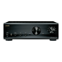
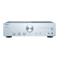
Why is there no sound coming from my Onkyo Amplifier A-9377?
- GGina WardJul 26, 2025
If the MUTING indicator is flashing, press the [MUTING] button on the remote controller to unmute the Onkyo A-9377. Also ensure that all audio plugs are fully inserted, the inputs and outputs of all components are correctly connected, the speaker cable polarity is correct, the correct input source is selected, no cables are bent or damaged, and the SPEAKERS selector is correctly set (not OFF). If you are using a turntable with an MC type cartridge, ensure you are using an MC head amp or MC transformer.