

J
james31Aug 18, 2025
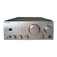
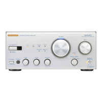
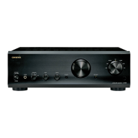
Why doesn't the remote controller work for my Onkyo A 9555 Amplifier?
- BBethany FernandezAug 18, 2025
If your Onkyo Amplifier remote controller isn't working: * Ensure the batteries are installed with the correct polarity. * Install new batteries, avoiding mixing different types or old and new ones. * Make sure the remote isn't too far from the A-9755/A-9555 and there are no obstructions between them. * Ensure the A-9755/A-9555 isn't exposed to direct sunlight or inverter-type fluorescent lights; relocate if needed. * If the A-9755/A-9555 is in a rack or cabinet with colored glass doors, the remote may not work reliably when the doors are closed.