Do you have a question about the Onkyo A-9050 and is the answer not in the manual?
Details the procedure for setting the amplifier for shipping.
Verifies the normal operation of speaker relays and sound output.
Checks the functionality of remote control and RI operations.
Verifies automatic audio input detection and power on/off behavior.
Tests the 12V trigger input and output functionality.
Checks the unit's response to voltage protection triggers.
Verifies the unit's response to current protection triggers.
Visual breakdown of the amplifier's external and major internal components.
Detailed visual breakdown of internal components and assembly.
Further detailed visual breakdown of internal components and assembly.
High-level overview of the amplifier's functional blocks and connections.
Detailed schematic of the amplifier's audio processing circuits.
Schematic detailing the power amplification stage of the amplifier.
Schematic of the amplifier's display and control interface circuitry.
Schematic of the amplifier's digital signal processing and control circuits.
List of semiconductor components used in the amplifier.
List of screws, legs, and other chassis-related hardware.
List of cabinet parts, knobs, plates, and covers.
List of coils, fuses, and switches used in the amplifier.
List of parts required for packing the unit.
List of included accessories and warranty information.
List of semiconductor components on specific PC boards.
| Output level | 175 mV |
|---|---|
| Damping factor | 60 |
| Amplifier class | A |
| Output impedance | 2200 Ω |
| Audio output channels | 2.0 channels |
| Peak power per channel | 75 W |
| Signal-to-Noise Ratio (SNR) | 110 dB |
| Total Harmonic Distortion (THD) | 0.08 % |
| AC (power) in | Yes |
| Audio (L/R) in | 5 |
| Audio (L/R) out | 1 |
| Digital audio coaxial in | 2 |
| Speakers connectivity type | RCA |
| Purpose | Home |
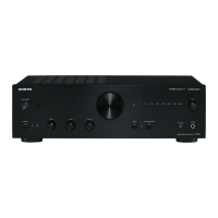
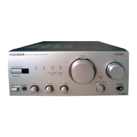
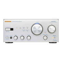
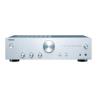
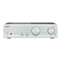
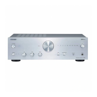
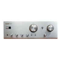
| Product color | Silver |
| Volume control | Rotary |
| Connectivity technology | Wired |
| AC input voltage | 230 V |
| AC input frequency | 50 Hz |
| Power consumption (standby) | 0.3 W |
| Power consumption (typical) | 160 W |
| Package weight | 10500 g |
| Depth | 330.3 mm |
|---|---|
| Width | 435 mm |
| Height | 139 mm |
| Weight | 820 g |